
Author: WECC REMTF[1]
The WECC generic models were designed for transmission planning studies that involve a complex network, and a large set of generators, loads and other dynamic components. The objective is to assess dynamic performance of the system, particularly recovery dynamics following grid-side disturbances such as transmission-level faults. In this context, WECC uses positive-sequence power flow and dynamic models that provide a good representation of recovery dynamics using integration time steps of one quarter cycle. This approach does not allow for detailed representation of very fast controls and response to imbalanced disturbances. It should be noted that generic dynamic models for inverter-based generator tend to produce a short-duration (a cycle or shorter) voltage spike at fault inception or clearing. These spikes should be ignored in most cases, as they do not represent the performance of actual hardware. They are simply a consequence of the model’s limited bandwidth, integration time step, and the way current injection models interface with the network solution.
Contents
Power Flow Representation
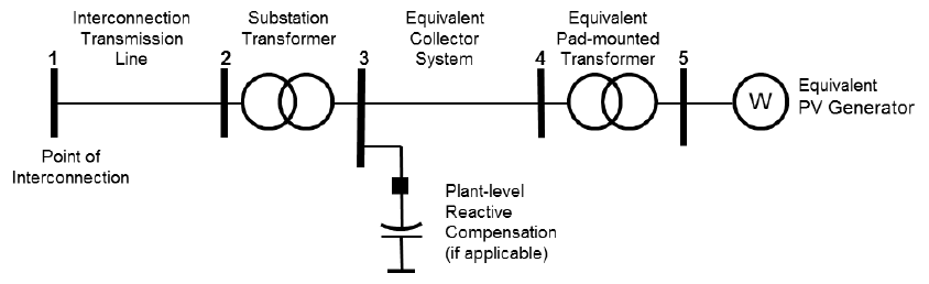
The WECC generic dynamic models described in this article assume that the PV generators are represented explicitly in power flow, representing a single large plant or the aggregated output of multiple smaller plants connected to distribution systems. For bulk system studies, it is impractical and unnecessary to model the collector system network inside the plant to the level of detail shown in figure on the right. In accordance with the WECC PV Plant Power Flow Modeling Guide, PV power plants must be represented by a simplified system consisting of one or more equivalent generators and unit transformers, equivalent collector system, substation transformer, and plant-level reactive support system, if present. For most PV plants, the single-generator equivalent model is adequate for bulk-level power flow and dynamic simulations. The WECC PV Plant Power Flow Modeling Guide also describes a methodology to derive the parameters for the single-machine representation, including a way to derive the collector system equivalent from design data.
Similarly, it is impractical to represent the large number of PV systems connected to distribution systems. When it is necessary to study the effects of distributed PV generation in a given area, the aggregated PV generation could be represented at a suitable transmission node by an equivalent generator, preferably behind an equivalent station transformer and equivalent medium voltage feeder. The dynamic models suggested for distributed PV plants are simpler than the dynamic models used for PV power plants.
Implications of Collector System Equivalencing
It is important that the equivalent impedance of the collector system be represented in dynamic simulations. Since PV systems typically extend over a large geographical area, the electrical impedance between the terminals of each PV system and the point of interconnection could be significantly different, leading to a diverse dynamic response. It is not possible to capture this level of detail with a single-machine equivalent. The same argument applies to situations where multiple distributed PV systems are aggregated into an equivalent generator. Therefore, it should be understood that the modeling approach provides an indication of the average response of the inverters, as opposed to the response of any particular inverter in the plant.
Active and Reactive Power Control
Average irradiance over a large PV plant can change appreciably during the span of a typical dynamic simulation (up to 30 seconds). By default, the WECC generic models assume a fixed reference generator output in the solved power flow case. Presently, there is no provision for incorporating simulation of irradiance variability in large-scale system studies. The generic models do allow for the specification of active power control, including ramp rate limits, frequency response and active/reactive power priority during voltage dips. Reactive power capability and response characteristics are an important consideration in system studies. A variety of reactive power control modes can be implemented in a PV power plant. Very large PV systems typically control voltage at the point of interconnection. Smaller plants are typically operated in power factor control mode. During a dynamic event, the reactive power response is the combined contribution of fast inverter response (in cycles) and slower supervisory control (in seconds) via the plant controller.
Fault Ride-Through and Representation of Protection Limits
An important part of a dynamic performance evaluation is whether the PV system will trip off line for a given voltage or frequency disturbance. The equivalent representation and simplified dynamic models described here are not recommended for evaluation of fault ride-through. Whether or not an inverter will ride through a voltage disturbance depends on the type of fault and the magnitude of the remaining voltage at the inverter terminals. The control actions that affect the behavior of the inverter during the span of a short fault are generally not modeled in detail in the generic dynamic models. This limitation is acceptable because system studies focus on the characteristics of the dynamic recovery, rather than on system conditions during the fault. Considering that terminal voltage can vary significantly across the plant, a single machine representation has obvious limitations with respect to assessment of voltage ride through.
Model parameters
As with any other equipment, appropriate parameters must be selected to represent the dynamic behavior of the corresponding PV plant. Default parameters provided are intended only for model testing, and do not represent any particular project. Consistent with established WECC practice, input from the plant operator and equipment manufacturer is required to correctly parametrize the model (Periodic model validation is also required). This is also true for the power flow representation.
References
- ↑ WECC REMTF, WECC PV Power Plant Dynamic Modeling Guide, March 2014, [Online]. Available: http://www.wecc.biz/committees/StandingCommittees/PCC/TSS/MVWG/20140318/Lists/Presentations/1/WECC%20Solar%20Plant%20Dynamic%20Modeling%20Guidelines%20-%20DRAFT%2020140310.pdf. [Accessed June 2014 ].