The term generic model refers to non-proprietary dynamic models that can be used to represent wind turbine generators (WTGs) with similar physical and control topology, regardless of the manufacturer. Recognizing the need for generic wind turbine generator (WTG) models, Western Electricity Coordinating Council (WECC) through its Renewable Energy Modeling Task Force (REMTF) has led a comprehensive effort to develop generic positive – sequence WTG dynamic models suitable for grid planning studies.[1] These models have now been implemented and validated in at least two widely used commercial transient stability simulation programs, Power System Simulation for Engineering (PSSE) and Positive Sequence Load Flow (PSLF). The generic WTG models are being updated and/or superseded by more up-to-date models as additional information becomes available.
Contents
Background
The overall process for developing generic WTG models typically initiates from a sophisticated three-phase, PSCAD-type model, with detailed representation of the very fast dynamics associated with the electronic components. This type of model is needed by manufacturers for detailed analyses and design. These models often need to be proprietary and vendorspecific, and include features not required for bulk power system analyzes. From these PSCAD-type models, positive sequence detailed transient stability models are derived by manufacturers to perform dynamic analyses. These detailed models also contain features that are not needed for typical transient stability studies; furthermore, the availability of these models is also often restricted. In order to circumvent the limitations associated with the general accessibility of WTG models, four prototype generic WTG models were developed by simplifying a detailed transient stability model. For instance, GE’s WTG models were used as the basis to develop the generic Type III and Type IV WTGs. To accomplish this, essential features likely to be common to different WTGs were retained, e.g., pitch controller, whereas others that are more proprietary in nature were simplified, e.g., the power coefficient curve.[1]
In principle, generic WTG models should exhibit the following characteristics: a) allow for an easy exchange of model data between interested parties, b) facilitate comparisons of system dynamic performance between different simulation programs, c) allow for the implementation of WTG models in different simulation programs, and d) provide a mechanism by which manufacturers can tune the model parameters to best represent their equipment, without having to reveal proprietary information.[1]
The design guidelines and modeling assumptions established for the generic models include:
- The models are intended for the simulation of events in a time associated with typical transient stability simulations, i.e., ten to twenty seconds.
- It is assumed that in the simulation time frame the wind speed remains constant.
- The models are not designed for use in simulations that involve severe frequency excursions.
- The models allow for the use of a single mass (equivalent to the generator and turbine inertias) or two separate masses.
- The models are suitable for representing individual WTGs or the equivalent of a wind power plant.
- The main model components do not include protective functions. These functions are to be modeled externally.
In addition, for the generic WTG models of Types 1, 2 and 3, the dynamics associated with the turbine and generator inertias are included within the Wind Turbine Model. This was done to facilitate the per unit representation of a twomass inertial model and the computation of the shaft stiffness. This representation is in contrast with the transient stability models of synchronous generators which typically include the inertia of the machine.
Over the years, the notion of generic models has been advanced significantly, driven by efforts to standardize models for WTGs and wind power plants (WPPs). In North America, recent activities on generic model development are led by the Renewable Energy Task Force (REMTF) of the Western Electricity Coordinating Council (WECC), in coordination with manufacturers and software developers. The International Electrotechnical Commission (IEC) is currently working on standardized WTG and WPP model specifications, which will further guide model implementation activities. Despite the progress that has been made, it is recognized that additional effort is required. The existing generic models must be refined over time, and eventually should become standard models, similar to standard models for other power system components.
Structure
First generation generic simulation models for all four turbine types are currently available as part of the main model libraries for the two most widely used commercial power system simulation tools in North America. These tools are Siemens PTI – Power System Simulation for Engineering (PSSE) and GE – Positive Sequence Load Flow (PSFL). This Section summarizes the model description, nomenclature, and function for all four turbine types as described in user manuals of PSLF [2] and PSSE [3]. The work behind the development of the generic models has been documented in different publications and workshops [4] [5] [6].
Generic Type I Model
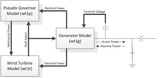
The type 1 wind turbine (wt1) is represented by three generic models in PSLF. These models are wt1g, wt1t, and wt1p. The wt1g model includes the generator dynamics. The wt1t model includes the single or double mass shaft compliance model. Finally, the wt1p model contains the pseudo governor model. In this arrangement, the turbine model computes the shaft speed from the electrical and mechanical torques provided by the generator and pseudo-governor models. The generator is a standard induction generator; however, unlike a conventional generator model, it contains no mechanical state variables for the machine rotor – these are included in the wind turbine model. Type 1 WTGs typically include requires reactive compensation, i.e., a capacitor bank, at the machine terminals. The user must represent shunt compensation separately in power flow.
Similar to its counterpart in PSLF the type 1 wind turbine (wt1) is represented by three generic models in PSSE. These models are WT1G, WT12T, and WT12A. The WT1G model includes the induction generator dynamics. The WT12T model includes the double mass shaft compliance model. Finally, the WT12A model contains the pseudo governor model.
Generic Type II Model
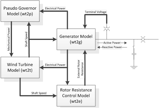
The type 2 wind turbine (wt2) is represented by four generic models in PSLF. These models are wt2g, wt2t, wt2e and wt2p. The wt2g model includes the generator dynamics. The wt2t model includes the wind aerodynamic model and the single or double mass shaft compliance model. The wt2p includes the pitch controller model. Finally, the wt2e model contains the rotor resistance control model for wound rotor induction wind turbine generator. The generator model represents an induction generator with provisions for adjusting its rotor resistance via the resistance controller. This controller uses rotor speed and generator electrical power as inputs. It computes the resistance to be added to the rotor in the generator model. The wind turbine and pseudo governor models are the same models as those used to represent the generic Type1 WTG.
The type 2 wind turbine ((wt2)) is represented by four generic models in PSSE (similar to PSLF). These models are WT2G, WT2E, WT12T, and WT12A. The WT2G model includes the generator/converters model. The WT2E contains the electrical control model. The WT2T model includes the wind turbine model. Finally, the WT2A model contains the pseudo governor model.
Generic Type III Model
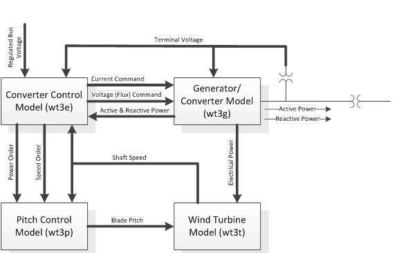
The type 3 wind turbine (wt3) is represented by four generic models in PSLF. These models are wt3g, wt3t, and wt3e. The wt3g model includes the generator and converters dynamics. The wt3t model includes the wind aerodynamic model. Finally, the wt3e model contains the real and reactive control models. The generic Type 3 generator/converter model is the equivalent of the generator and field converter, and provides the interface between the WTG and the network. The mechanical state equations are included in the turbine model; furthermore the flux dynamics are eliminated to reflect the rapid response of the converter. The net result is an algebraic, controlled-current source that computes the required injected current into the network in response to commands from the electrical control model. The model also incorporates low voltage power logic and fast-acting converter controls that mitigate over-voltages by reducing reactive current output. The input signals into the generator/converter model are passed through simple low-pass filters. These filters are approximations to the actual fast electronic control system; each filter consists of a first order transfer function with a time constant of twenty milliseconds.
The type 3 wind turbine (WT3) is represented by four generic models in PSSE (similar to PSLF). These models are WT3G1, WT3T1, WT3E1 and WT3P1. The WT3G1 model includes the generator and converters dynamics. The WT3T1 model includes the wind aerodynamic model and the single or double mass shaft compliance model. The WT3P1 includes the pitch controller model. Finally, the WT3E1 model contains the real and reactive control models.
_wind_turbine_generator.png)
Generic Type III Model (Phase II)
The model is based on on the detailed GE’s wind turbine model [7] [8] and consists of four components: generator/converter, converter control, wind turbine, and pitch control. Several simplifications were made to the GE WTG model, for instance: the active power control and GE’s WindINERTIA control were excluded. In the generic Type 3 generator/converter model, the flux dynamics are eliminated to reflect the rapid response of the converter to the higher level commands from the electrical controls.
It is known that the control structure of the existing generic Type 3 WTG does not allow for representation of the full range of possible control implementations for doubly-fed asynchronous generators (DFAG). Parameter sensitivity analyses have shown that the existing model does not have sufficient degrees of freedom to adjust the model response. Since the generator is represented simply as excitation voltage behind an equivalent sub-synchronous reactance, similar to a synchronous generator, it is difficult to reproduce active and reactive current modulation that occurs in Type 3 WTG during a grid disturbance.[9][10]
Through various discussions, particularly at the IEC TC88 WG27 and WECC REMTF meetings, proposed changes to this model have been made in order to make it more suitable for simulating a wider range of possible type 3 WTGs
Generic Type IV Model
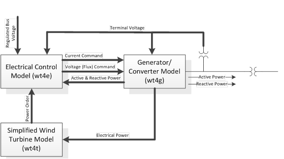
The type 4 wind turbine (wt4) is represented by three generic models in PSLF. These models are wt4g, wt4t, and wt4e. The wt4g model includes the generator and converters dynamics. The wt4t model includes the wind aerodynamic model and the wind turbine model. Finally, the wt4e model contains the real and reactive control models. The converter control model shown computes the active and reactive power to be delivered to the system. The overall structure of the controller is somewhat similar to the Type 3 WTG reactive power control model but it includes logic to determine the current limits. The objective of these limits is to prevent the combination of the real and reactive currents from exceeding converter capability. Depending upon the value of a user-specified P-Q priority flag, either real or reactive power has priority. This flag is dependent upon the equipment features selected, and is normally dictated by the host system grid code.
The type 4 wind turbine (WT4) is represented by four generic models in PSSE. These models are WT4G and WT4E. The WT4G model includes the generator and converters dynamics. The WT4E model contains the electrical control model for the type 4 wind generator.
_wind_turbine_generator.png)
Generic Type IV Model (Phase II)
This model consists of three components: generator/converter, converter control, and wind turbine. The model is based on GE’s wind turbine model[11]. The generator model is very similar to the Type 3 generator model. The main difference is that the model takes as inputs both reactive and active current commands.
The active power control seems to be too simple, for the existing first generation type 4 model. Also, the reactive power control of the existing first generation generic model does not cater to various reactive power injection options of various designs. Through various discussions, particularly at the IEC TC88 WG27 and WECC REMTF meetings, proposed changes to this model have been made in order to make it more suitable for simulating a wider range of possible type 4 WTGs.
Summary
A list of available simulation modules for both PSSE and PSLF is shown in tables below. Although there are differences in the program implementation, the models are functionally equivalent and have the same set of parameters. Note that the models for certain WTG types only require two modules (e.g., WT4); while others require four modules (e.g., WT3).
| Type 1 | Type 2 | Type 3 | Type 4 | |||||
|---|---|---|---|---|---|---|---|---|
| Software Platform | PSLF™ | PSS®E | PSLF™ | PSS®E | PSLF™ | PSS®E | PSLF™ | PSS®E |
| Generator | wt1g | WT1G1 | wt2g | WT2G1 | wt3g | WT3G | wt4g | WT4G |
| Excitation | —— | —— | wt2e | WT2E1 | wt3e | WT3E | wt4e | WT4E |
| Turbine | wt1t | WT12T1 | wt2t | WT12T1 | wt3t | WT3T | wt4t | —— |
| Pitch Controller | wt1p | WT12A1 | wt2p | WT12A1 | wt3p | WT3P | —— | —— |
The models presented here have slightly different names in the various commercial software platforms simply because of the inherent naming conventions used by the software vendors. The table below gives a cross-reference for the model names in the three most commonly used tools in WECC and many other US regions.
| Model Name in the Model Specification Document | Model Name in GE PSLF™ | Model Name in Siemens PTI PSS®E | Model Name in PowerWorld Simulator |
|---|---|---|---|
| New Models (developed 2011 – 2014) | |||
| REGC_A | regc_a | REGCAU1 (V33); REGCA1 (V34) | REGC_A |
| REEC_A | reec_a | REECAU1 (V33); REECA1 (V34) | REEC_A |
| REEC_B | reec_b | REECBU1 (V33); REECB1 (V34) | REEC_B |
| REEC_C | reec_c | REECCU1 (V33 & V34) | REEC_C |
| REPC_A | repc_a | REPCTAU1 & REPCAU1 (V33); REPCTA1 & REPCA1 (V34) | REPC_A |
| WTGT_A | wtgt_a | WTDTAU1 (V33); WTDTA1 (V34) | WTGT_A |
| WTGAR_A | wtga_a | WTARAU1 (V33); WTARA1 (V34) | WTGA_A |
| WTGPT_A | wtgp_a | WTPTAU1 (V33); WTPTA1 (V34) | WTGP_A |
| WTGTRQ_A | wtgq_a | WTTQAU1 (V33); WTTQA1 (V34) | WTGTRQ_A |
| WT1P_B | wt1p_b | not yet part of the standard model library | WT1P_B |
| Existing Models (developed prior to 2009) | |||
| WT1G | wt1g | WT1G1 | WT1G & WT1G1 |
| WT2G | wt2g | WT2G1 | WT2G & WT2G1 |
| WT2E | wt2e | WT2E1 | WT2E & WT2E1 |
| LHVRT | lhvrt | VTGTPAT | LHVRT |
| LHFRT | lhfrt | FRQTPAT | LHFRT |
Shaft Dynamics
Shaft dynamics can have a significant effect on dynamic stability, particularly for Type-1 and Type-2 WPPs connected to a weak part of the network. The turbine models for the Type-1, Type-2 and Type-3 WTGs (wt1t, wt2t, and wt3t) allow for a single-mass of a two-mass model. For the single mass model, only the inertia and damping needs to be specified. For the two-mass model, the ratio of turbine to generator inertia, first shaft torsional resonant frequency and shaft damping factor need to be specified. Type-3 and Type-4 WTGs effectively isolate the generator and turbine shaft dynamics from the grid. The turbine model for the Type-3 WTG (wt3t) is included primarily to emulate the effect of aerodynamics on the dynamic performance.[12]
References
- ↑ 1.0 1.1 1.2 Working Group Joint Report – WECC Working Group on Dynamic Performance of Wind Power Generation & IEEE Working Group on Dynamic Performance of Wind Power Generation of the IEEE PES Power Stability Controls Subcommittee of the IEEE PES Power System Dynamic Performance Committee, “Description and Technical Specifications for Generic WTG Models – A Status Report.”
- ↑ GE Energy, PSLF Version 17.0_07 User’s Manual, Schenectady, NY, 2010.
- ↑ Siemens Energy, Inc., PSSE Wind Model Library, Schenectady, NY, 2009.
- ↑ Y. Kazachkov and S. Stapelton, “Does the Generic Dynamic Simulation Wind Turbine Model Exist?,” in WindPower, Denver, CO, 2005.
- ↑ A. Ellis, E. Muljadi, J. Sanchez-Gasca and Y. Kazachkov, “Generic Models for Simulation of Wind Power Plants in Bulk System Planning Studies,” in Proc. Power Engineering Society General Meeting, Detroit, MI, 2011.
- ↑ A. Ellis, Y. Kazachkov, E. Muljadi, P. Pourbeik and J. Sanchez-Gasca, “Description and Technical Specifications for Generic WTG Models – A Status Report,” in IEEE Power Systems Conference and Exposition (PSCE), Phoenix, AZ, 2011.
- ↑ Nicholas W. Miller, Juan J. Sanchez-Gasca, William W. Price, Robert W. Delmerico, “Dynamic Modeling of GE 1.5 and 3.6 MW Wind Turbine-Generators for Stability Simulations”, Proc. Power Engineering Society General Meeting 2003. Toronto, Ontario. July 2003.
- ↑ K. Clark, N. W. Miller, J. J. Sanchez-Gasca, Modeling of GE Wind Turbine-Generators for Grid Studies, Version 4.5, April 2010, General Electric International, Inc.
- ↑ Thomas Ackermann, Wind Power in Power Systems, 2nd Edition, Wiley, May 2012 (ISBN: 978-0-470-97416-2)
- ↑ J. Fortmann, S. Engelhardt, J. Kretschmann, C. Feltes and I. Erlich, “Validation of an RMS DFIG Simulation Model According to New German Model Validation Standard FGW TR4 at Balanced and Unbalanced Grid Faults”, 8th International Workshop on Large-Scale Integration of Wind Power into Power Systems as well as on Transmission Networks for Offshore Wind Farms, Bremen, Germany, 2009.
- ↑ K. Clark, N. W. Miller, J. J. Sanchez-Gasca, Modeling of GE Wind Turbine-Generators for Grid Studies, Version 4.5, April 2010, General Electric International, Inc.
- ↑ Price, W.W., Sanchez-Gasca, J.J., “Simplified wind turbine generator aerodynamic models for transient stability studies” Power Systems Conference and Exposition, 2006. PSCE ’06. 2006 IEEE PES, Oct. 29 2006 – Nov. 1, 2006.
