
Electrical Systems and Control
Induction machines are the energy conversion devices of choice in commercial wind turbine design. In addition to their robustness and reliability, they provide a “softer” coupling between the grid and the mechanical system of the turbine. Wind turbine manufacturers have also moved beyond the basic induction generator systems with technologies for improving control and overall efficiencies. These technologies have a definite impact on the electrical and dynamic performance of wind turbines, even to the extent of masking or overriding the dynamic characteristics that would normally be associated with rotating machinery. Almost all of the wind turbines deployed in large wind generation facilities in the U.S. over the past decades can be generally described by one of the following configurations:
|
Mechanical Systems and Control
Mechanically, the turbine must be protected from rotational speeds above some value that could lead to catastrophic failure. Mechanical brakes are provided for stopping the turbine in emergency conditions, but are not used in normal operations. Controlling the power (and hence, torque) extracted from the moving air stream is the primary means for protecting the turbine from over-speed under all but emergency shutdown conditions. In fairly steady conditions, the power extracted from the air stream by the turbine blades can be characterized by:
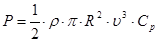
- ρ = air density (nominally 1.22 kg/m3)
- R = radius of area swept by the turbine blades
- υ = speed of moving air stream
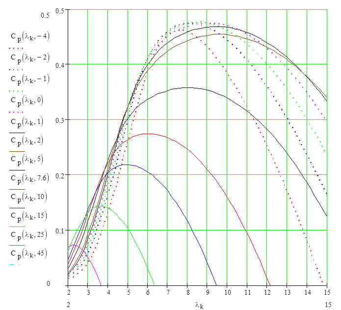
- Cp = “coefficient of performance” for the composite airfoil (rotating blades)
Cp itself is not a constant for a given airfoil, but rather is dependent on a parameter λ, called the tip-speed ratio, which is the ratio of the speed of the tip of the blade to the speed of the moving air stream. Since wind speed and air density cannot be controlled, and the radius of the blades is fixed, the performance coefficient is the only means for torque control. In some wind turbines, blades are designed so that Cp falls dramatically at high wind speeds. This method of aerodynamic torque control is known as stall regulation, and is limited to preventing turbine over-speed during extreme gust conditions and limiting maximum shaft power in winds at or above the rated value. Large wind turbines employ a more sophisticated method of aerodynamic torque regulation that has benefits in addition to preventing mechanical over-speed. The performance coefficient can also be changed by adjusting the “angle of attack” of the blades, as is done on some modern propeller-driven aircraft. Blade pitch adjustment allows the energy capture to be optimized over a wide range of wind speeds (even if the rotational speed of the shaft is relatively constant), while still providing for over-speed protection through large adjustments in pitch angle.
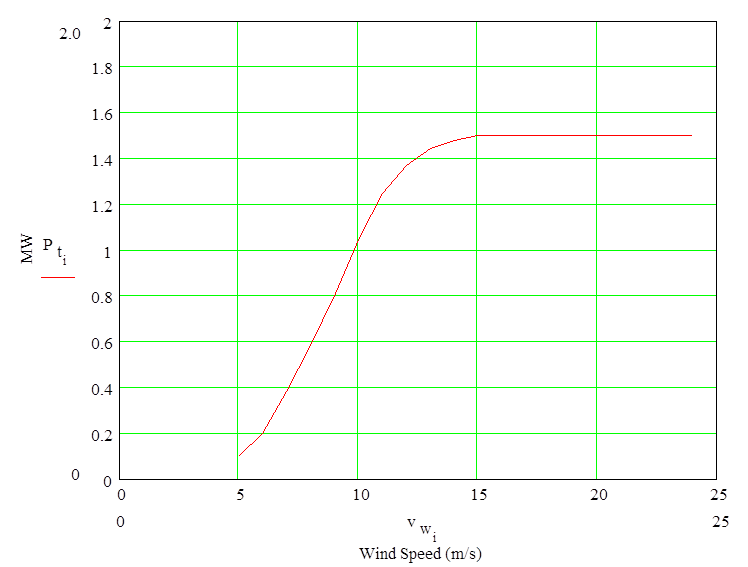
The pitch of the turbine blades is controlled by an actuator in the hub that rotates each blade about a longitudinal axis. The inertia of the blade about this axis and the forces opposing such a rotation of the blades are not negligible. Pitching of the blades, therefore, does not happen instantaneously, with the dynamics governed by the longitudinal inertia of the blades, forces acting on the blade (which can be wind speed and pitch dependent), and the torque capability of the pitch actuator mechanism. A “quasi-static” blade performance does not account for turbulence effects, blade vibration with respect to the average speed of rotation, or other asymmetries such as tower shadowing. It does, however, provide a much simpler means of incorporating the otherwise very complex details of the aerodynamic conversion process into models for electrical-side studies of the turbine. The overall conversion of wind energy to electric power is normally described by a turbine “power curve”, which shows turbine electrical output as a function of steady wind speed. Such a representation is accurate only for steady-state operation, since the inherent dynamics of the mechanical and electrical systems along with all possible control functionality is neglected.
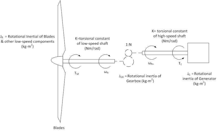
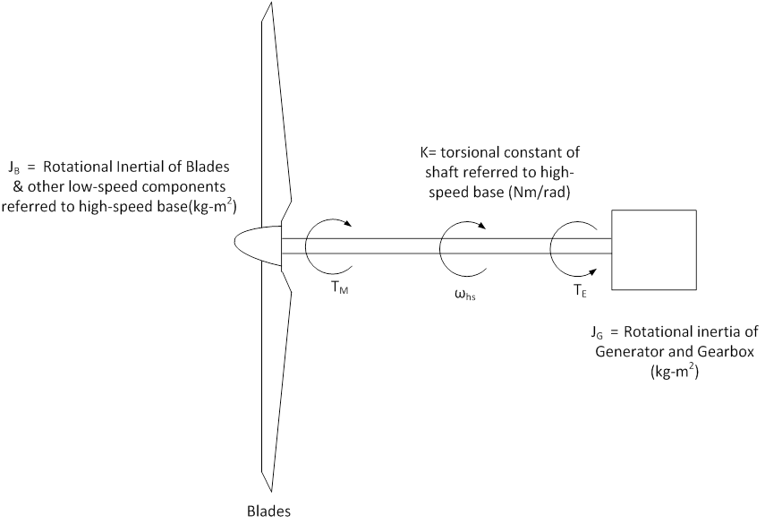
Rotational speeds of large wind turbines are partly limited by maximum blade tip speed, and so for megawatt-class turbines with long blades are relatively low, in the 15 to 30 rpm range. With conventional electrical generators, a gearbox is necessary to match the generator speed to the blade speed. The resulting mechanical system, then, has low-speed and high-speed sections, with a gearbox in between. An even simpler representation is achieved, where the gearbox inertia is added to the inertia of the generator, and all components are referred to the high-speed shaft by the square of the gear ratio. For megawatt-scale turbines, the mechanical inertia is relatively large, with typical inertia constants (H) of 3.0 seconds or larger (the inertia constant for the generator only will typically be about 0.5 s). The mechanical inertia is an important factor in the dynamic behavior of the turbine, because the large inertia implies relatively slow changes in mechanical speed for both normal variations in wind speed and disturbances on the grid. In addition, the various control systems in the turbine may utilize turbine speed as an input or disturbance signal, so that large inertia will then govern the response time. With a two-mass mechanical model, there will be one oscillatory mode. With relatively flexible drive shafts in large wind turbines, the natural frequency of this primary mode of oscillation will be in the range of 1 to 2 Hz.