
Power system operators around the world are pushing the limits of integrating inverter-interfaced generation from wind and solar to very high levels approaching 100%, including in South Australia, Ireland, the Hawaiian Islands, and Great Britain. These and several others have identified the value of grid-forming (GFM) technology as the key enabler to support this transition. They have integrated several GFM battery energy storage systems to ensure stable operation of their grids, and they are also the front runners in developing preliminary and non-mandatory specifications for GFM resources. On the other end of this spectrum are large power system operators with moderate but ever-increasing levels of inverter-based resources (IBRs) that are still able to maintain grid reliability using synchronous generators present in their system. There is an ongoing discussion on the cost of inaction and missed opportunity by these large operators towards the deployment of GFM resources. This is especially true for the hundreds of gigawatts of battery storage capacity in interconnection queues for which the GFM capability can be enabled relatively easily through software changes. A common refrain from large power system operators is: what is GFM and why do we need it?
While the need for GFM functionality can be identified by performing grid integration studies for a future targeted system, the answer to the question “what is GFM?” is more complex. The grid operators that have started adopting the GFM technology have not necessarily resolved this question; they rely on vendors to provide GFM solutions without providing any quantifiable specifications. Until we precisely answer the question of “what is GFM?”, we cannot define how we will test the performance of GFM resources or develop their specifications.
What is Grid-Forming?
The North American Electric Reliability Corporation (NERC) has defined the GFM control of IBRs as “controls with the primary objective of maintaining an internal voltage phasor that is constant or nearly constant in the sub-transient to transient time frame.” But despite our having a definition, the lack of consensus on “what is GFM?” comes about because GFM is often described not as a single capability or a service, but rather as a type of an IBR that can offer a suite of services. These range from instantaneous power response for grid stabilization and droop-like primary frequency control to blackstart, damping, and fault current contribution.
However, such over-prescription of capabilities that a GFM IBR should offer is detrimental to the goal of encouraging rapid adoption of GFM technologies. Some of the capabilities that have been associated with GFM IBRs—such as droop response, positive damping, and fault current contribution—can also be provided by grid-following (GFL) IBRs (Table 1). On the other hand, some capabilities that are used to describe the GFM technology, such as droop response and blackstart, cannot be provided even by some conventional power plants with synchronous generators. For example, nuclear units and synchronous condensers (SynCons) do not provide droop-like primary frequency control, and some conventional power plants are not blackstart capable, but they all are indeed GFM resources.
It is important to identify minimum core functionalities that constitute the GFM behavior; other capabilities can be deemed advanced, but they should be optional when a GFM resource is procured, depending on the system needs.
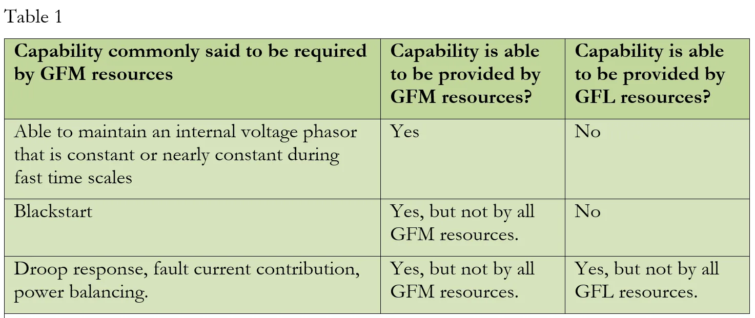
Illustration of Grid-Forming Controls
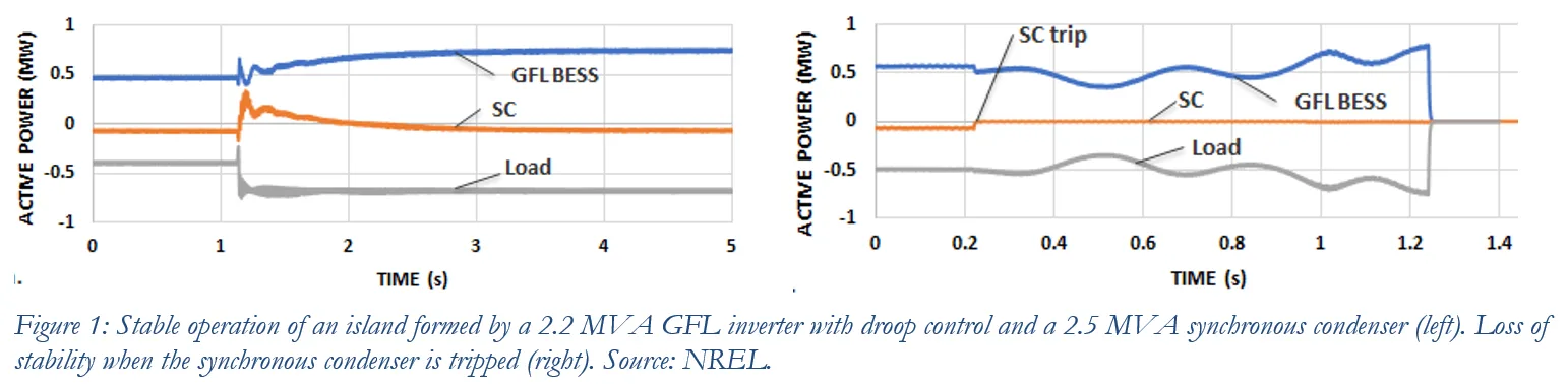
These points will be illustrated with a simple example. Figure 1 shows operation of an island at the Flatirons Campus of the National Renewable Energy Laboratory (NREL) including no GFM IBRs. The island was formed by a 2.2 MVA inverter with GFL controls, a 2.5 MVA SynCon, and a 3 MVA load bank. The GFL inverter is coupled to a 1 MW/1 MWh battery energy storage, and it was configured to provide 5% active power droop response. As shown in the left figure, during a 300-kW step change in the load, the GFL inverter and the SynCon act together to effectively stabilize the system. The SynCon quickly takes over the additional load by releasing its kinetic energy and slowing down its speed because of its voltage source behavior. The GFL inverter acts slowly and takes over the additional load in steady state because of its droop control, returning the power consumption of the SynCon (to support losses) to a pre-disturbance level. The right side of Figure 1 shows another test, where the SynCon is tripped and the island loses its stability because of the absence of any other GFM resource in the system. These tests show that SynCon maintains stability primarily through its voltage source behavior in fast time scales without performing power balancing through droop control—the latter is performed by the GFL inverter.
Figure 2 shows results during similar experiments when the battery inverter is operated with GFM controls. Unlike the GFL mode, the inverter quickly dispatches active power following a load transient in the GFM mode. Moreover, the battery inverter can maintain stable operation of the island even after the SynCon is tripped because of its GFM capability.
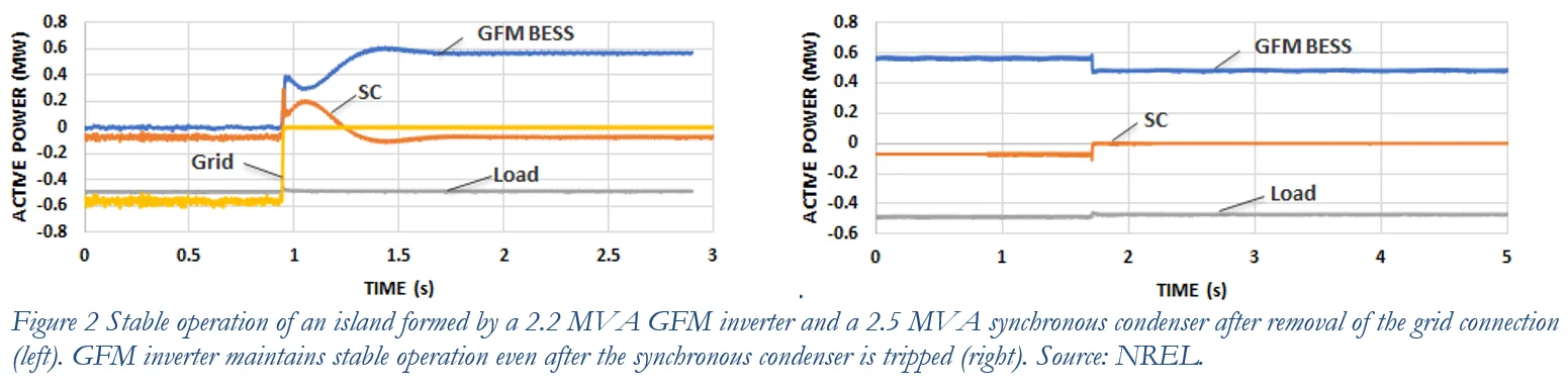
The island experiment shows that the essence of a GFM resource is its ability to behave as a constant voltage source in fast time scales so that it quickly and naturally dispatches active and/or reactive power to stabilize the grid following a disturbance. All other capabilities—such as droop response, blackstart, positive damping, power sharing, voltage balancing, and fault current contribution—do not need to be provided by all GFM resources; in fact, many of them can also be provided by GFL resources.
New Testing Methods Required to Evaluate the Performance of GFM IBRs
Testing of a GFM resource should focus on testing its capability to behave as a voltage source behind a reactor during fast time scales, particularly the capability of the internal voltage source to provide fast active and reactive power response during grid disturbances. Time-domain specifications can be defined for the rise time, settling time, magnitude, and duration of the active and reactive power responses during a disturbance in the grid voltages, such as voltage phase angle jumps, high rate of change of frequency events, and voltage magnitude jumps.
Frequency-domain specifications can also be used to “specify” the internal voltage source of a GFM IBR using the frequency scans of transfer functions from the frequency and magnitude of the grid voltage to active and reactive power output of the IBR. The main advantage of frequency-domain testing is that the sub-transient and transient time scales can be easily translated to a frequency range where GFM performance needs to be specified. Moreover, frequency-domain specifications can also be tested independently of the characteristics of the grid at the terminal of an IBR, which is not possible with time-domain specifications. It is worth mentioning, however, that the frequency-domain testing is fundamentally small-signal in nature. Hence, it cannot test the capability of an IBR to dispatch large active and reactive power response when the IBR is operating near its physical limits. Hence, it is recommended to use both time-domain and frequency-domain specifications for characterizing the GFM capability of IBRs.
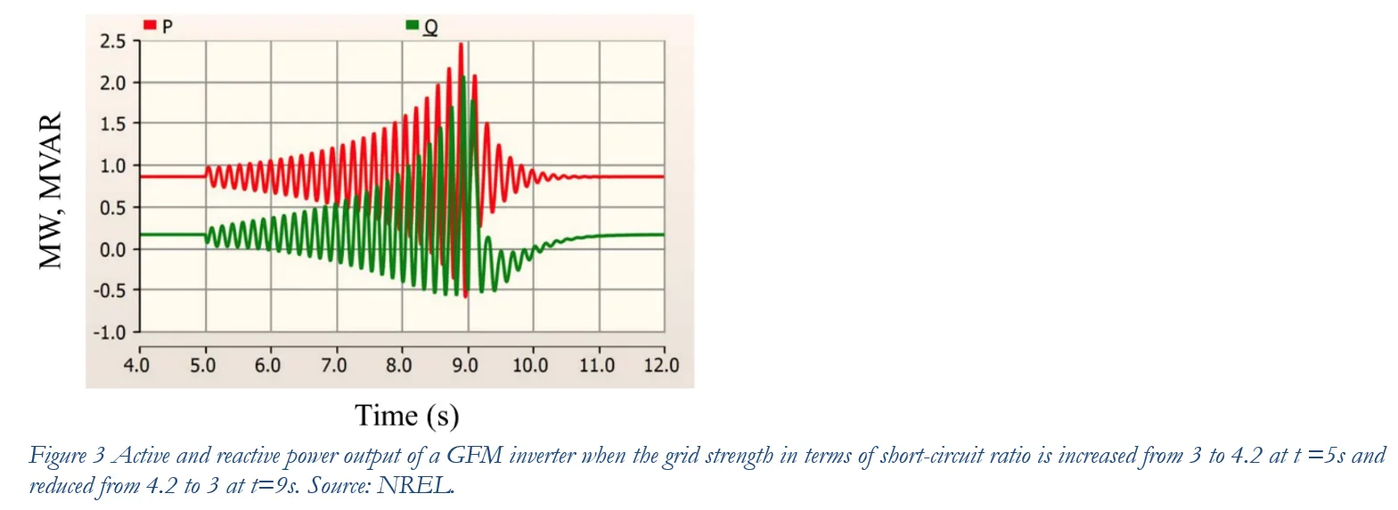
Setup for testing GFM inverters might need to be different from that for GFL inverters. Because of the internal voltage source behavior, GFM inverters are expected to work stably under weak grid conditions. However, the same voltage source behavior might limit their ability to operate with strong grids. Figure 3 shows the power output of a GFM inverter during different grid conditions—clearly the inverter becomes unstable when the grid strength or short-circuit ratio increases above 4. Depending on whether a GFM inverter is designed to work stably with an extremely strong grid (aka stiff voltage source) or not, an additional reactor might be required between the inverter and the grid simulator used for testing the inverter.
All GFM Resources Need Not Provide All Capabilities of Synchronous Generators
Power systems around the world are transitioning to a low-carbon future. GFM can either be just one additional capability previously provided by synchronous machines and now demanded from IBRs, or it can be an opportunity to demand all desirable features of synchronous generators from IBRs and some more; perhaps the correct answer lies somewhere in-between. I personally prefer to consider GFM as a single capability or a service, which is the ability of an IBR to hold its internal voltage phasor constant during sub-transient to transient time scales following a grid disturbance.
Shahil Shah
Senior Research Engineer
NREL