
General Characteristics
In a PV system, the PV array converts solar radiation directly into direct current (DC) electricity. At a given solar irradiance and cell temperature, the current and power output of the array is a function of terminal voltage. The voltage Vs. current characteristic (or IV curve) is nonlinear. There is a voltage level at which maximum power is extracted for a given irradiance level. The available current and power varies in proportion to the effective irradiance incident on the plane of the array. Temperature effects are secondary compared to irradiance, with lower temperature yielding higher performance. Irradiance level, ambient temperature, wind speed affect cell temperature. To maximize energy capture, some PV arrays are mounted on sun-tracking structures.
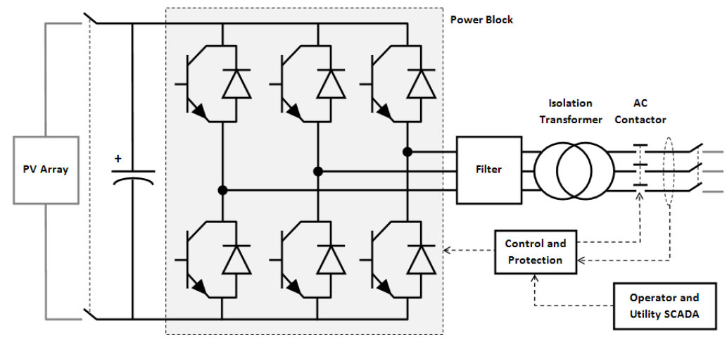
An inverter is used to couple the PV array to an AC network. One of the control objectives for the inverter is maximum power tracking, which means that the voltage across the inverter inputs is controlled such that the PV array operates at the maximum power point. The inverter also regulates ac current magnitude very fast, even during disturbances, to ensure that current and temperature limits of the switching elements are not exceeded. Inverters also have the capability to change power factor, within the current magnitude limits. With appropriate controls implemented, inverter-based reactive power capability could be used to achieve reactive power control objectives at the plant level. The integrated isolation transformer and filter reduce harmonic injection into the grid. Additional filtering may be applied at the DC side to reduce ripple effects, and at the inverter output to reduce high frequency electromagnetic emissions.
A grid converter monitors the AC voltage and frequency to modulate converter behavior and disconnect the inverter from the grid when voltage and frequency tolerances are exceeded. The IEEE 1547-2003 standard defines voltage and frequency thresholds for residential and commercial PV systems and other distributed energy resources. In addition, IEEE 1547 requires that distribution-connected PV inverters de-energize after faults on the Area Electric Power System (EPS) circuit and prior to circuit reclosure. Inverters must “cease to energize” within 2 seconds of the formation of an electrical island (i.e., when a portion of the grid disconnects from the bulk system). This feature is commonly referred to as “anti-islanding”. PV inverters connected to the customer side of the meter are required to have certification that they comply with these and other safety and grid compatibility requirements. UL 1741 is an example of certification that addresses this issue.
References
- ↑ 1.0 1.1 WECC REMTF,WECC Guide for Representation of Photovoltaic Systems In Large-Scale Load Flow Simulations, August 2010, [Online]. Available: http://www.wecc.biz/committees/StandingCommittees/PCC/TSS/MVWG/REMTF/Solar%20Documents/WECC%20PV%20Plant%20Power%20Flow%20Modeling%20Guidelines%20-%20August%202010.pdf. [Accessed February 2013].