
Author: National Renewable Energy Laboratory[1]
While fixed-speed wind turbines are simple and robust, they have a significant disadvantage: they cannot optimally extract power from the wind. It would be preferable to have the generator continue to output rated power at high wind speeds. To achieve this, variable-speed wind turbines are employed. While largely relying on the same concepts as fixed-speed wind turbines at lower-than-rated wind speeds, they typically incorporate blade pitch and output power controls to optimize power extraction at higher-than-rated wind speeds. The Type-2 turbines use rotor resistance control to achieve output power control. This article discusses the concept of rotor resistance control, its basis in machine theory and the induction machine equivalent circuit, a few methods of achieving optimal power output based on rotor resistance control, the implementation of the control methods using a modified version of the fixed-speed wind turbine model, and provides a discussion of the results obtained from the modified model. Stall regulation is employed rather than pitch regulation in order to focus on the rotor resistance controller action.
The complete model has been implemented in PSCAD/EMTDC for the purposes of this article. However, the model is straightforward to implement using other popular simulation packages such as MATLAB/Simulink. The model is based on parameters from a Vestas V63 1.5-MW turbine.
Contents
Rotor Resistance Control Concept
| Turbine Properties | |
|---|---|
| Turbine make | Vestas V63 1.5MW |
| Regulation method | Pitch control (disabled) |
| Rotor diameter | 63 m |
| Hub height | 64 m |
| Number of blades | 3 |
| Cut-in wind speed | 4 m/s |
| Cut-out wind speed | 20 m/s |
| Rated wind speed | 13 m/s |
| Rotor speed | 19/15 rpm |
Induction machines were invented over a hundred years ago, and are fairly well understood. The basic principle behind their operation is electromagnetic induction. Voltages applied to a multiphase AC stator winding result in currents which produce a rotating magnetic field. This field induces voltages (and therefore currents) in the rotor circuit. The interaction between the stator produced field and the rotor induced currents produces torque. If the induction machine is driven by a prime mover at a speed greater than its synchronous speed, it acts as a generator. The rotor circuit may consist of bars short-circuited through end rings in the case of squirrel cage machines, or in the case of wound-rotor machines, multiphase windings accessible through slip rings and brushes. Since the rotor windings are accessible, modifications to the rotor circuit are possible. One of these possible modifications is changing the rotor resistance. Revisiting the induction machine equivalent circuit is necessary to evaluate the impact of changing the rotor resistance on the torque and power associated with the machine.
Induction machine equivalent circuit
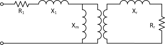
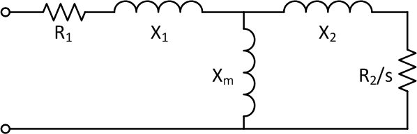
The equivalent circuit in steady state for an induction machine is similar to that of a transformer. The equivalent circuit can be represented by only one phase since in steady state, all three phases are balanced and thus the equivalent circuit is identical. R1 and X1 are the stator series resistance and reactance, respectively, while Xm is the magnetizing reactance. The rotor resistance Rr and reactance Xr can be referred to the stator side using the ideal transformer’s turns ratio with R2 and X2 representing the referred quantities. This eliminates the transformer. Here s refers to the slip. The rotor windings are shorted, i.e. no external resistance is present. Based on the equivalent circuit, we can construct a Thevenin equivalent model, from which the following equations for air gap power and torque may be derived[2]
where,
\(R_{TH}=Re(Z_{TH})=Re\left(\frac{jX_m(R_1+jX_1)}{R_1+j(X_1+X_m)}\right)\)
\(X_{TH}=Im(Z_{TH})=Im\left(\frac{jX_m(R_1+jX_1)}{R_1+j(X_1+X_m)}\right)\)
Here VTH is the Thevenin-equivalent voltage at the equivalent circuit terminals, and RTH and XTH are Thevenin-equivalent resistance and reactance, respectively. Slip s varies from 1 at zero rpm, to 0 at synchronous speed.
Effect of rotor resistance change on equivalent circuit and torque and power equations
So far external resistance has not been considered, i.e., the rotor windings have been assumed to be shorted. A resistor in each phase is required since the equivalent circuit represents one phase of a balanced three-phase circuit. Due to the transformer turns ratio, the value of Rext will not necessarily be equal to the actual resistance value used to implement the external rotor resistance. The power and torque equations are modified as follows
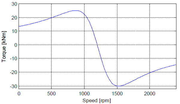
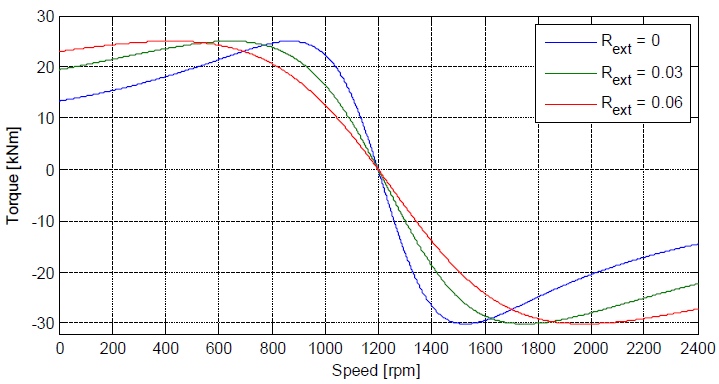
A desired value of torque can now be achieved at many different speeds, by varying the external rotor resistance. For motor operation, higher rotor resistance yields high starting torque, but also causes increased running losses during normal operation, due to power dissipated in the rotor resistance. In a wound rotor induction machine, an external resistance may be inserted into the rotor circuit during starting, and when operating under load, the external resistance can be shorted out, thus achieving both objectives: high starting torque and low running losses. The rotor resistance controller in a variable-speed wind turbine is more complicated, and requires consideration of the aerodynamics. Development and testing of rotor resistance control schemes.
Methods of Rotor Resistance Control
Control of power output of a Type-2 turbine can be accomplished by varying the rotor resistance. The objective of a rotor resistance controller in this situation is to seek the operating point at which power extraction from the wind is maximized, and also prevent the power extracted from exceeding the machine’s ratings. The fixed-speed model has to be modified in order to model variable speed operation. One basic control method is the PI control. The focus is on development and testing of a PI controller for rotor resistance control.
Model Implementation
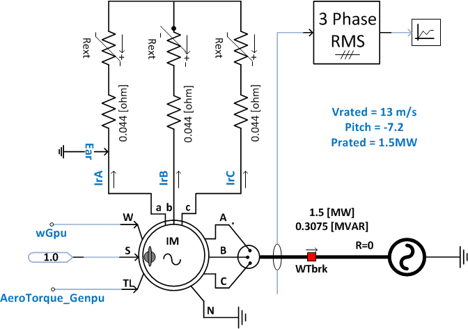
In PSCAD/EMTDC, a wound-rotor induction machine model is available. The same machine parameters as are used for the fixed-speed machine are used here, with some small modifications. The internal rotor resistance is “pulled out” and placed explicitly on the rotor circuit, in series with the controlled external resistances.
| Induction generator ratings | |
|---|---|
| Rated MVA | 1.5 MVA |
| Rated Voltage | 0.69 kV line-to-line |
| Number of poles | 6 |
| Rated frequency | 60 Hz |
| Stator/rotor turns ratio | 0.379 |
| Induction generator parameters | |
| Stator winding resistance | 0.005 pu |
| Wound rotor resistance (int) | 1e-6 pu |
| Wound rotor resistance (ext) | 0.0021 pu |
| Stator leakage inductance | 0.08 pu |
| Squirrel-cage inductance | 0.0478 pu |
| Magnetizing inductance | 6.8 pu |
| Angular moment of inertia | 0.578 s |
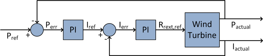
Another modification to the fixed-speed model is the inclusion of a control block for external resistance control. This control block employs Proportional-Integral or PI controllers. PI controllers are standard for wind turbine control. A PI controller attempts to minimize the error between a measured process variable and a desired reference value by calculating and outputting a control action that can adjust the process in a rapid manner to keep the error minimal. In practice, this takes the shape of a feedback loop. By tuning the proportional and integral gains, the speed of response of the controller and the magnitude of the overshoot can be chosen appropriately for the desired control action. Tuning of PI controllers is fairly straightforward[3]. The difference between the control methods lies in the choice of measured process variable for generating the error signal. The controller described here is similar to that employed by real-world turbines. The controller action is based on two measured quantities; output real power (primary) and rotor currents (secondary). The controller employs two loops; an outer loop for real power control which is a relatively slow-changing quantity and an inner loop which reads the output of outer loop controller as set-point, and controls the rapidly changing rotor currents. The measured power signal is compared to the desired power, and the error drives a PI controller. The output of the PI controller is the reference rotor current. This reference current is compared with the measured rotor current and the error is fed to another PI controller. The output of this PI controller is the rotor resistance value for achieving desired rotor current (and thus output power).
Two-loop PI controller based on output power and rotor current
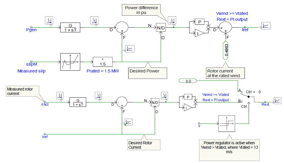
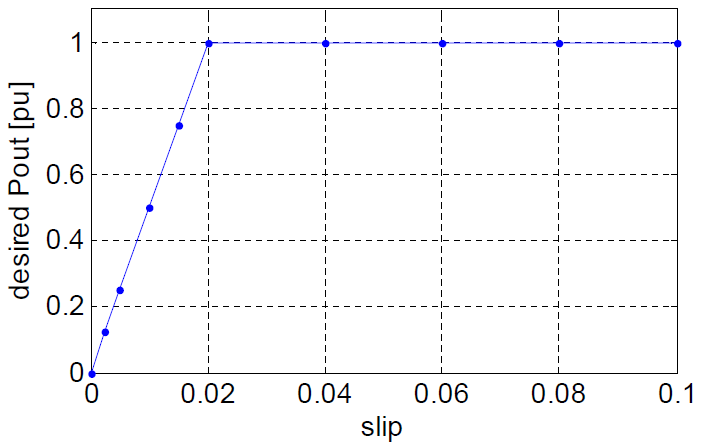
The most straightforward way of controlling the output power is to use the measured power value as the process variable for comparison. A reference power signal is generated by measuring the machine slip, and using a non-linear characteristic (desired Pout vs. Slip) to find the desired value of power for that value of slip. This reference power value is compared with the measured power and the error signal is fed to the PI control. The output of the PI controller is the reference rotor current (rms) that is necessary to achieve the reference output power. This reference current is compared with the actual measured rotor currents (rms), and the error between them drives a second PI controller. The output of this second PI controller is the external rotor resistance required to maintain the rotor currents (and thus the generator power output) at its rated value. The power controller is inactive when the wind speed is below the rated wind speed. It only becomes active when wind speed exceeds rated wind speed. This is due to the disabling of the pitch controller for the purpose of simplicity.
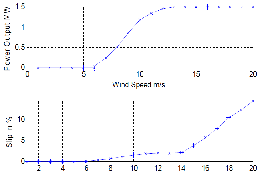
The resulting power curve of the wind turbine is flat at wind speeds higher than rated, as was desired. By comparison, the curve for the fixed-speed wind turbine droops at higher-than-rated wind speeds. The results show that a PI controller using measured power and rotor currents as the input variables is a credible solution for maintaining rated power at higher than rated wind speeds.
| Data for power curve, slip, rotor resistance, speed, and torque | |||
|---|---|---|---|
| Vwind (m/s) | Pout (MW) | Slip (%) | Rext (Ω) |
| 6 | 0.035 | 0.06 | 0 |
| 7 | 0.231 | 0.329 | 0 |
| 8 | 0.503 | 0.7 | 0 |
| 9 | 0.852 | 1.175 | 0 |
| 10 | 1.179 | 1.619 | 0 |
| 11 | 1.342 | 1.839 | 0 |
| 12 | 1.447 | 1.982 | 0 |
| 13 | 1.5 | 2.05 | 0 |
| 14 | 1.5 | 2.19 | 0.00285 |
| 15 | 1.5 | 3.76 | 0.0358 |
| 16 | 1.5 | 5.65 | 0.0734 |
| 17 | 1.5 | 7.98 | 0.12468 |
| 18 | 1.5 | 10.52 | 0.17533 |
| 19 | 1.5 | 12.394 | 0.21214 |
| 20 | 1.5 | 14.63 | 0.257 |
Dynamic Response
To demonstrate the model’s ability to reproduce wind turbine dynamics, a test was created. The wind turbine was operated with a constant wind speed (13 m/s). This wind speed was chosen to be the rated value. A voltage sag on the grid was simulated, and the real and reactive power response of the wind turbine was observed. Note that this is not an implementation of low-voltage ride through (LVRT), but rather a test of dynamic response. The grid voltage drops from 1 p.u. to 0.8 p.u. at t=15s, and the sag persists for 18 cycles (0.3 seconds). The intent of the test is to show that the model does indeed respond to events occurring in the dynamic timescale and that the response of the machine to this event is realistic. Obtained results show that the model does indeed respond to the grid event as expected. As expected, the step changes in the grid voltage magnitude when the sag begins and ends cause an immediate response. Note that the speed experiences a greater change (approximately 5%) as compared to the fixed-speed wind turbine. The real power and reactive power outputs experience a disturbance too, however, the disturbance is once again qualitatively and quantitatively different from the response of the fixed-speed wind turbine due to the rotor resistance controller. The results also show that a mechanical oscillation occurs after the sag ends, and that the oscillation eventually damps out.
.png)
References
- ↑ NREL, Dynamic Models for Wind Turbines and Wind Power Plants (NREL/SR-5500-52780), October 2011, [Online]. Available: http://www.nrel.gov/docs/fy12osti/52780.pdf. [Accessed February 2013].
- ↑ S. Chapman and Y. Man, Electric machinery fundamentals. McGraw-Hill, 1985
- ↑ B. Kuo, Automatic control systems. Prentice Hall, 1995