
Author: WECC WGMG[1]
This article contains technical recommendations for power flow representation of wind power plants (WPP) in the Western Electricity Coordinating Council (WECC), and was prepared by the WECC Renewable Energy Modeling Task Force (REMTF). REMTF is also advancing the state of the art on WPP generic dynamic modelimplementation.
Contents
- 1 Brief Background
- 2 Single-Machine Equivalent Representation
- 3 Modeling during post transient and power flows
- 4 References
Brief Background
Wind Power Plant Topology
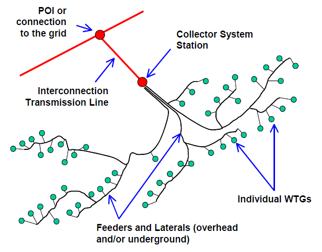
A wind power plant (WPP) consists of many individual wind turbine generators (WTGs) tied to a medium voltage collector system, and connected to the transmission system at the interconnection point. Modern utility-scale WTGs have nameplate rating ranging from 1 MW to 4 MW. Terminal voltage is about 600 V. A step-up transformer, generally a pad-mounted unit, connects each WTG to a medium-voltage collector system operating at 12 kV to 34.5 kV. The collector system consists of one or several feeders connected together at a collector system station. One or more station transformers at the collector system station are used to achieve transmission system voltage. Unless the collector system station is adjacent to the interconnection point, an interconnection transmission line is needed. Reactive compensation in the form of mechanically switched capacitors and continuously variable devices such as STATCOMs or Static Var Systems (SVS) may be installed at the collector system station. Depending on the type of WTG, shunt reactive compensation at the WTG terminals may be installed for power factor correction. The amount and nature of reactive compensation is driven by interconnection requirements and collector system design considerations, including voltage regulation and losses.
Types of Wind Turbine Generators
Early vintage WTGs were simple cage induction generators prone to tripping during grid disturbances. Until recently, tripping was considered preferable from the transmission system point of view, considering the small capacity of WPPs and their tendency to increase reactive power consumption and delay voltage recovery following electrical fault events. However, WPPs are becoming increasingly prominent in terms of size, especially in certain areas of the system. Also, they are located in sparsely populated windy areas, where the transmission system tends to be weak. Today, WPPs are expected to tolerate grid disturbances and contribute to overall power system reliability. In response to evolving wind generator interconnection standards, WTGs have improved rapidly with respect to steady-state and dynamic performance. WTG manufacturers have introduced numerous variations of electrical and mechanical controls as well as drive train and generator configuration. Most of modern WPPs have the ability to provide reactive power support to the system by using reactive capability built into the WTGs, or through external reactive compensation systems.
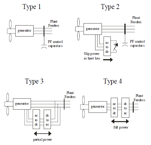
Despite the large variety of utility-scale WTGs available in the market, each can be classified into one of four basic types, based on the grid interface (Dynamic performance for each type of WTG is different), as listed below:
- Type 1 – Cage rotor induction generators
- Type 2 – Induction generators with variable rotor resistance
- Type 3 – Doubly-fed asynchronous generators with rotor-side converter
- Type 4 – Full-power converter interface
Single-Machine Equivalent Representation
The WGMG recommends the use of the single-machine equivalent representation to model WPPs in WECC base cases. Based on industry experience, this representation is also considered adequate for positive-sequence transient stability simulations.
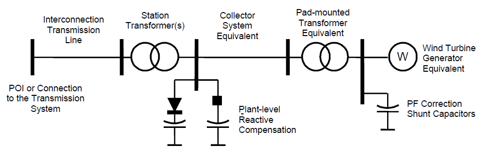
The interconnection transmission line, station transformer(s) and plant-level reactive compensation should be represented explicitly, according to established industry practice. Equivalent representations are needed for the collector system station and WTGs.
- The equivalent generator and associated power factor correction capacitors represents the total generating capacity and reactive compensation of all the WTGs in the WPP.
- The equivalent generator step-up transformer (pad-mounted transformer) represents the aggregate effect of all WTG step-up transformers
- The equivalent collector system branch represents the aggregate effect of the WPP collector system, and should approximate real power losses and voltage drop out to the “average” WTG in the WPP.
Established power flow modeling principles should be applied to WPP representation, although there are some differences that require especial attention. Single-machine equivalent model parameters can be derived from preliminary data. Preliminary data should be replaced with as-built data when such data becomes available, certainly shortly after commissioning. Powerflow model data should be validated from time to time by comparing the model to actual data, consistent with WECC and NERC requirements and methodologies. However, as of the date this guide was written, specific WPP testing and model validation guidelines have not been adopted for use in WECC.
With the proper model parameters, this model should approximate WPP powerflow characteristics at the interconnection point, collector system real and reactive losses and voltage profile at the terminals of the “average WTG” in the WPP. There are some limitations, however. Due to collector system effects, terminal voltage of individual WTGs could vary widely. WTGs that are closest to the interconnection point may experience significantly different terminal voltage compared to WTGs that are electrically farthest from the interconnection point. In actual operation, terminal voltage of some WTGs may reach control or protection limits, resulting in different terminal behavior, or tripping. During the design stage, or in special circumstances, it may be reasonable to use a more detailed representation of the collector system. However this type of detail usually is not relevant for largescale simulations.
The following guidelines should be considered to model each of the components of the WPP single-machine equivalent representation.
Interconnection Transmission Line
Standard data includes line voltage, line length, and line parameters (R, X and B). In some cases, the interconnection transmission line may be operated at a voltage level lower than the system voltage at the interconnection point, but higher than the collector system voltage. This requires an additional transformation stage and perhaps more shunt compensation to make up for higher reactive losses. Economics may favor this approach depending on a number of factors.
WPP Station Transformer
A WPP contains one or several station transformers at the collector system station. Station transformers should always be modeled explicitly. They represent the majority of the impedance between the interconnection point and the terminals of the equivalent WTG. Standard data includes transformer terminal voltage, MVA ratings (ONAN/FA/FA), percent impedance on the transformer’s self-cooled (ONAN) MVA base, and X/R ratio. Positive-sequence impedance for these types of transformers is in the range of 7 to 10%, with X/R ratio in the range of 40 to 50.
Plant Level Reactive Compensation
Many WPPs have reactive compensation installed at collector system station, consisting of mechanically switched capacitors, continuously acting reactive power devices (such STATCOM or SVS). The plant-level reactive power compensation system can be controlled to meet one of three possible steady-state control objectives:
- Closed-loop voltage control – Maintain voltage schedule within the reactive power capability of the WPP, over a certain range of real power output. Controlling voltage at the interconnection point is likely to cause large reactive power swings for small voltage changes if the WPP is connected to a strong transmission system. Reactive droop compensation can be used to improve reactive power stability without compromising voltage control benefits. A small voltage hysteresis may be allowed in some situations. For instance, the requirement may be to regulate voltage at the interconnection point within 1% or 2% of schedule when WPP output exceeds 20% of rated capacity.
- Power factor control – Maintain power factor at the interconnection point close to a specified level. For instance, the requirement may be to maintain power factor between 0.98 lead and unity at the interconnection point.
- Reactive power control – Maintain reactive power flow within some specified limits. For instance, the requirement may be to limit reactive power flow at the interconnection point to 5 or 10 Mvar, in either direction.
Some WTGs have the capability to participate in steady-state voltage control and meet a portion or all the interconnection requirements. However, this capability is not always implemented in the field (see Equivalent WTG Representation).
To properly model plant level reactive compensation, it is very important to establish what reactive control mode has been implemented, as well as the type of WTGs and compensation devices that are used. The following should be kept in mind to properly model reactive compensation devices:
- Discrete shunt capacitors should be modeled as constant impedance devices in power flow, to capture voltage-squared effects.
- Continuously variable reactive power devices such as STATCOMs should be modeled as a reactive power generator in power flow. Reactive limits should be set to the continuous rating of the device, consistent with power flow time frame. Some STATCOM manufacturers allow a transient overload capability in the 2 to 3 second time frame. This can be taken into account in dynamic simulations. However, the temporary overload capability should not be used in power flow.
- Ideally, SVCs should be represented as “svd” (static Var devices) with the appropriate number and size of steps. However, standard positive-sequence simulation programs require that this type of devices be represented as generators in power flow before conducting dynamic simulations. Therefore, it is recommended that SVCs be represented as generators in power flow to avoid having to convert a potentially large number of svd to generators in order to conduct dynamic simulations. Until this modeling issue is resolved, it is recommended that SVCs be represented as generators in power flow.
Equivalent Collector System
WPP collector systems consist of relatively long medium voltage feeders and laterals. Factors considered in feeder design include cost, real power losses, and voltage performance. A typical design goal is to keep average real power losses below 2%. At full output, real power losses can be higher, in the 3% to 5% range. Land use agreements usually favor the use of underground feeders despite the higher cost. For that reason, equivalent collector system X/R ratio tends to be low and line susceptance is high compared to typical overhead circuits. The equivalent collector system impedance also tends to be small compared to the station transformer impedance, but is not insignificant.
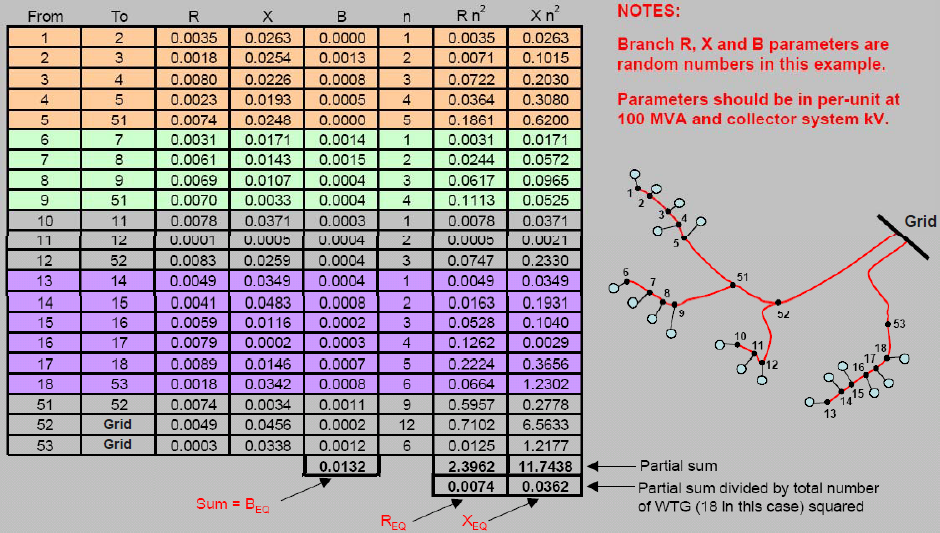
A simple method developed by National Renewable Energy Laboratory (NREL) can be used to derive equivalent impedance (Zeq) and equivalent susceptance (Beq) from conductor schedule as follows:[2]
\(Z_{eq} = R_{eq}+jX_{eq}=\cfrac{\sum_{i=1}^I Z_in_i^2}{N^2}\) \(B_{eq} = \sum_{i=1}^I B_{i}\)where I is total number of branches in the collector system, Zi and ni are the impedance (Ri + jXi) for ith branch, and N is the total number of WTGs in the WPP. As stated before, the equivalent impedance computed in this manner approximates real and reactive losses seen by the “average WTG” in the WPP. This calculation can be easily implemented in a spreadsheet. Figure on the right shows a simple example with I = 21, N = 18.
Larger WPPs have lower Zeq and higher Beq considering that additional circuits are needed to handle larger currents. However, this relationship does not always hold. Table bellow shows some examples of actual equivalent collector system parameters for several WPP of different nameplate capacity and different collector system configuration. Per unit parameters are on a 100 MVA and collector system kV base.
| Plant size | Collector voltage | Feeder | R (pu) | X (pu) | B (pu) |
|---|---|---|---|---|---|
| 100 MW | 34.5 kV | All underground | 0.017 | 0.014 | 0.030 |
| 100 MW | 34.5 kV | 33% overhead (carrying 100% of WTG) | 0.018 | 0.079 | 0.030 |
| 110 MW | 34.5 kV | All underground | 0.012 | 0.011 | 0.036 |
| 200 MW | 34.5 kV | Some overhead | 0.007 | 0.025 | 0.055 |
| 200 MW | 34.5 kV | 25% overhead (carrying 50% of WTG) | 0.010 | 0.039 | 0.099 |
| 300 MW | 34.5 kV | Some overhead | 0.005 | 0.020 | 0.085 |
| 300 MW | 34.5 kV | Some overhead | 0.006 | 0.026 | 0.150 |
| Note: per unit parameters are on a 100 MVA base and collector system kV base | |||||
Equivalent WTG Step Up or Pad-Mounted Transformer
WTG pad-mounted transformers are typically two-winding air-cooled transformers. The per-unit equivalent impedance (ZTeq) and the equivalent MVA rating (MVATeq) for the N identical WTG step-up transformers, each of which has impedance ZT on its own MVA base (MVAT), are computed as follows:
\(Z_{Teq} = Z_T\) \(MVA_{Teq} = N \times MVA_T\)Step-up transformers associated with modern utility-scale WTGs (1 to 3 MVA) have impedance of approximately 6% on the transformer MVA base, with X/R ratio of about 8.
Equivalent WTG Representation
For power flow simulations, the equivalent WTG should be represented as a standard generator. Real power level and reactive power capability must be specified according to the guidelines below.
Active Output Level
.png)
Generator interconnection studies are typically conducted with the WPP at full output. At the discretion of the transmission planner, WPPs in the study area that are included in the base case can be assumed to be at full output, or at some other output level, depending on the purpose of the study. The following should be taken into account:
- For regional transmission planning studies, it is recommended that the power level be established based on the average output level during the time frame of interest, unless specific high or low wind output scenarios are of interest. This approach allows for consideration of realistic load and resources balance over the study area. Average output during a certain time frame varies depending on the location of the WPP. For example, in the US desert southwest, WPP output tends to be low (5% to 15% of nameplate capacity) during the during peak summer load hours due in part to temperature-related wind turbulence. Average output increases during the evening hours (off peak load periods), as turbulence decreases. Average output is significantly higher during the spring and winter and fall. In locations near the coast, wind resource may be driven by other factors such land-water temperature differential, resulting in very different seasonal output patterns.
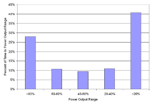
- Due to the steepness of WTG power curve or output versus wind speed characteristic, an individual WPP is likely to be at either low output (< 20% of nameplate capacity) or high output (> 80% of nameplate capacity) at any given time. Figure on the right shows an example of power output distribution for an individual WPP in the Pacific Northwest. This pattern tends to hold even for the aggregate output of wind farms that are in close proximity. Based on these observations may be reasonable to represent a WPP or group of WPPs installed in a certain region either off-line or at maximum power output. Again, the choice is dependent on the purpose of the study.
Reactive Power Capability and Power Factor Correction Capacitors
WTG reactive power capability is related to the type of WTG and the manner in which they are operated. The following guidelines apply:
- Type 1 and Type 2 WTGs are induction machines. In the range of 50% to 100% power level, uncompensated power factor typically ranges from 0.85 to 0.90 under-excited (consuming reactive power). Several stages of capacitors banks at the WTG terminals are normally applied to raise the power factor to approximately unity. In power flow, power factor correction capacitors should be modeled as fixed shunt devices, considering that that WPP power output is held constant in power flow studies. In the power flow model, reactive power consumption can be assumed to be ½ of the power output. A capacitor should be shown at the WTG terminals to compensate power factor to unity at nominal voltage. For example, for a 100 MW WPP at full output, both Qmin and Qmax would be set to -50 Mvar, and add a 50 Mvar shunt capacitor at the WTG terminals. Plant level reactive compensation may still be installed to meet interconnection requirements.
- Type 3 and Type 4 WTGs normally do not have power factor correction capacitors installed at the machine terminals. These WTGs are capable of adjusting power factor to a desired value within the rating of the generator and converter. They are also capable of voltage control at the interconnection point. When this functionality is implemented, the individual WTGs respond to a reactive power or power factor commands from an external plant-level controller. It should be kept in mind that, for commercial and other reasons, WTG-assisted steady-state voltage control functionality is not implemented or enabled in many WPPs with Type 3 or Type 4 WTGs. External reactive power compensation is often required to meet interconnection requirements, as discussed here. If these WTGs do not participate in voltage control, the equivalent generator should be assigned a fixed power factor, typically unity. (i.e., Qmin and Qmax would be set to 0). If the WTGs do participate in voltage control, then the equivalent generator should be assigned a reactive capability approximately equal to the aggregate WTG reactive power range. The WTG reactive power range is a function of power output. For example, consider a 100 MW WPP that employs Type 4 WTGs with specified power factor range +/-0.95 at full output. In this example, Qmin should be set to -33 Mvar and Qmax should be set to +33 Mvar. At an output level below rated, the reactive limits should be adjusted according to the WTG capability curve.
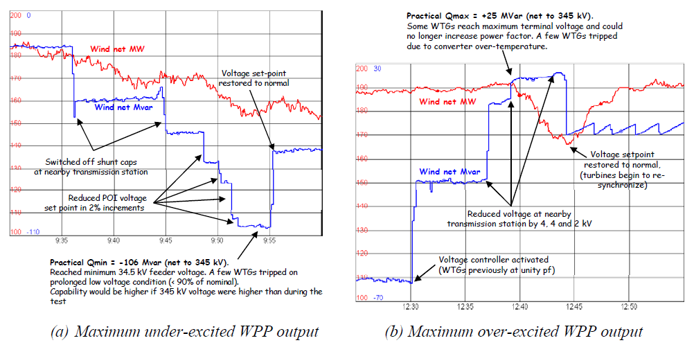
Due to collector system effects, some WTGs in the WPP will actually reach terminal voltage limits before reaching the nameplate reactive power limits. The net effect is that actual reactive power capability could be significantly less than the nameplate. The reactive power capability can be determined by field test or careful observation of WPP performance during abnormally high or low system voltage. For example, Figure on the right shows the results of field tests to determine the practical reactive limits of a 200 MW WPP. All measurements were made at the interconnection point. Taking into account the effect of transformer and collector system impedances, the reactive power limits of the equivalent WTG can be established. Currently, there are no industry standard guidelines for testing WPP steady-state reactive limits.
Modeling during post transient and power flows
Modeling of WPP generator and reactive compensation components should be consistent with WECC pos-transient methodology. Control devices that can complete switching or operation within 3 minutes (e.g., SVCs, STATCOMS and shunts under automatic control) should not be blocked. Devices that require operator action should be blocked. The equivalent WPP generator should have the Load Flag set to “1” to reflect the fact that the output should not change during a governor power flow.
References
- ↑ WECC WGMG, Wind Power Plant Power Flow Representation, May 2010, [Online]. Available: http://renew-ne.org/wp-content/uploads/2012/05/WECCWindPlantPowerFlowModelingGuide.pdf. [Accessed June 2014].
- ↑ E. Muljadi, A. Ellis, et al, “Equivalencing the Collector System of a Large Wind Power Plant”, IEEE Power Engineering Society Annual Conference, Montreal, Quebec, June 12-16, 2006.