
Author: EPRI[1]
This software was developed as part of the EPRI P173.00 Grid Performance and Modeling of Variable Generation and Evolving Power System Resources project in 2012. The motivation for developing the tool is to provide utilities with an easy and flexible tool for validating the models for wind turbine generators. This is a first release of the tool and is presently limited in its scope. It allows for parameter fitting and validation of type 3 and 4 wind turbine generator models using the latestgeneric models developed through EPRI‘s efforts in collaboration with the Western Electricity Coordinating Council (WECC) and the International Electrotechnical Commission (IEC). Supplemental funding was also provided by the Sandia National Laboratory for this work. The National Renewable Energy Laboratory also provided some supplemental funding towards the work involved in the development of the models. In future research the goal is to enhance the tool to allow for validation of aggregated wind plant models, and to further extend the tool to cater to solar photovoltaic systems as well.
Benefits and Value
The benefits of this software program are that it can be easily used to process disturbance data collected either from a digital fault recorder installed at a wind turbine generator in a wind power plant or factory test data for fault ride-through type tests performed in the factory. The benefit of using on-line disturbance monitoring data is that the models can be validated on a routine basis without the need to tamper with the equipment and its controls for staged tests.
| Operating System | |
|---|---|
| The software may be installed on any PC with a Windows XP, Vista or the Windows 7operating systems. The software is not supported on older operating systems such as Windows 2000 | |
| RAM | |
| At least 512MB RAM (1024MB recommended) | |
| Disk Space | |
| At least 500MB of disk space | |
| Processor | |
| Intel® Pentium® III processor or later, and AMD processors | |
| Miscellaneous | |
| Mouse, Keyboard and CD-ROM drive | |
| Assistance | |
| EPRI Customer Assistance Center (CAC) at 1-800-313-3774 (or email askepri@epri.com) |
Contents
- 1 Introduction
- 2 Program Installation
- 3 The WTGMV Software Tool General Program Description
- 4 Running WTGMV, Menu Selection and Program Usage
- 5 Tutorial for Using WTGMV
- 6 References
Introduction
Background
The use of power system simulation models for performing system wide planning and operational studies is a well established practice in today’s utility industry. There are three groups of models that combined to constitute a model of the entire power system for use by system planner and operators. These three groups are the model of the transmission system, the model of the loads and the model of the generation equipment. This tool is for use in developing and validating the models for wind turbine generators. The concept used is similar to other tools developed by EPRI that are presently well established and in use.
A detailed and comprehensive account of the design, control and modeling of the newly developed generic models that are utilized in this tool can be found here and here.
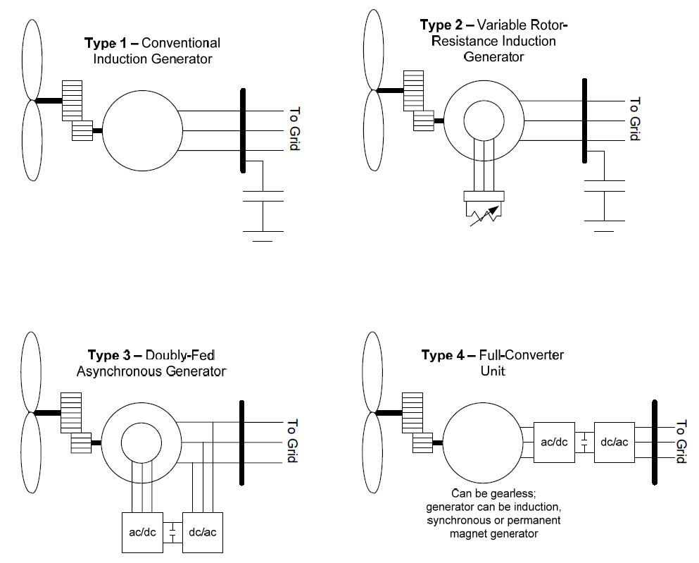
In general, the most commonly sold and installed technologies in today’s market (both in the US and overseas) tend to be the type 3 and 4 units – i.e. those based on power converters. All the major equipment vendors supply one or both of these technologies. There are, however, large numbers of the type 1 and 2 units in-service around the world, and so modeling them is also of importance. Some vendors do still supply the type 1 and 2 turbines as well. This first release of the WTGMV tool, however, covers only the two latest models developed for the type3 and 4 technologies. In future releases of the tool the type 1 and 2 models may be added to the tool as deemed necessary.
Also, this first release of the tool focuses on the validation/parameter derivation of a single wind turbine generator. In future releases we will be working towards the ultimate research goal of attempting to enhance the tool to allow for model validation of an aggregate wind power plant model based on measured disturbance data at the point of interconnection of the wind plant.
This user’s manual describes the use of the WTGMV tool for performing model validation, using disturbance data collected either from a digital fault recorder (DFR) or a phasor measurement unit (PMU) for a single wind turbine generator. Data obtained through tests in the factory of a single wind turbine generator may also be useful for this purpose.
The models used are the newly developed type 3 and 4 generic models. These models are of a modular format, that is several standard modules are used in specific combinations to constitute either a type 3 or 4 Wind turbine generator (WTG). The model specification documents have been made public through the Western Electricity Coordinating Council (WECC) Renewable Energy Modeling Task Force (REMTF).
Finally, a few items should be re-emphasized:
- This first release of the tool incorporates the newly developed generic models for the type 3 and type 4 WTG. It should be noted that this tool has been extensively tested using data for several vendors of WTGs using data from actual tests performed on single WTGs inside wind power plants.[2] If users identify issues or have suggestions base on use of WTGMV, such input is welcome and should be sent to ppourbeik@epri.com.
- The type 1 and 2 WTG models were not included in this release for two reasons:
- Proposed changes to these models have not yet been completely finalized – the type 3 and 4 were considered of higher priority by the industry groups working on these activities.
- We were unable to receive any measurement data for validating the type 2 models.
- We received some limited data for the type 1 models, which have not yet been fully analyzed.
- The present release is focused only on a single WTG. The plant level controls have not yet been incorporated into the tool for use in aggregated plant level model validation. This is a work in progress.
Program Installation


EPRI develops software using a number of third party software products and tools that run on various operating systems and server platforms. Reports from the software industry suggest there are known security issues with some products and systems. EPRI recommends that, if you are using EPRI software, you review its use with your Information Technology (IT) department and their overall strategy to ensure that all recommended security updates and patches are installed as needed in your corporation.
If you experience difficulties accessing the application after standard installation on Windows XP or Windows Vista, please consult your IT department personnel to have proper access permissions setup for your use.
IMPORANT NOTE: This tool was developed using The Mathworks Inc. MATLAB® program and MATLAB® Compiler. To use the tool one must installed MATLAB® Compiler Runtime (MCR). By installing the MCR you (the Licensee) are agreeing to the terms of the MCR Library License, you must not remove any references to this license from your system and cannot provide the MCR Library to any third parties or alter it in anyway.
There are two steps in installing the program:
- Installing the MATLAB® Compiler Runtime – this is needed to run the WTGMV executable since it is a set of MATLAB® script files that have been compiled into an executable using the MATLAB® Compiler.
- To install the tool WTGMV.
In general, the following system requirements are needed:
- At least 512MB RAM (1024MB recommended)
- At least 500MB of disk space
- Windows XP(Service Pack 1 or 2) – or Windows XP, or Windows 7, or Windows Vista
- Intel® Pentium® III processor or later, and AMD processors
- Mouse, Keyboard and CD-ROM drive
- A proper text editor to view and edit the output text files generated by WTGMV is highly recommended. One example of such text editor is TextPad Version 4.7.3 or higher. Another example is EditPlus. Both these editors have been tested and work very well with the standard text file output of WTGMV. The standard text editor in Windows (NotePad) will not work since it cannot properly read formatted text files. The more sophisticated Windows text editor, MicroSoft® WordPad Version 5.1, will have some minor formatting issues with the output files in some cases, however, it will display the output file.
The program has been tested on the following system configurations:
- Windows XP Professional (Service Pack 2) with Intel® Pentium® M, 1.6GHz, 2GB RAM.
- Windows XP Professional Version 2002 (Service Pack 3) with Intel® Core™2 Duo CPU P8400, 2.26 GHz, 1.86 GB RAM.
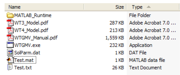
Open the installation CD by inserting the CD in your CD-ROM and opening it as a folder or drive. The following files/folders should be on the CD:
WARNING: The following procedure for installing the MATLAB® Compiler Runtime 7.10 components need only be followed once on a single computer for installing WTGMV or any other executable created with the MATLAB® Compiler version 4.1 R2009a. Therefore, if the user already has the MATLAB® Compiler Runtime 7.10 components from a previous installation, it should not be installed again. Once the MATLAB® Compiler Runtime 7.10 components have been installed on a PC, WTGMV can be executed in any folder on the PC that contains the four files WTGMV.exe, SolParm.dat, WT3_Model.pdf, WT4_Model.pdf and WTGMV_Manual.pdf.
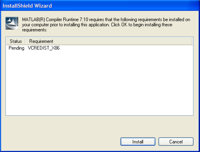
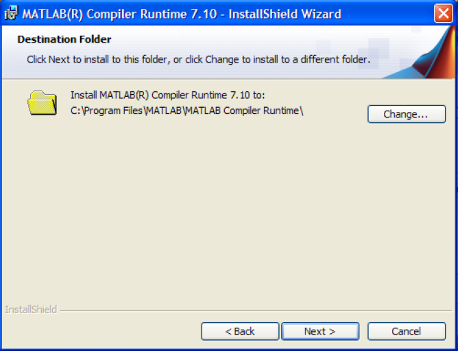
Open the folder “Matlab Runtime” and double click (to execute) the program “MCRInstaller.exe”. The installation wizard will start.
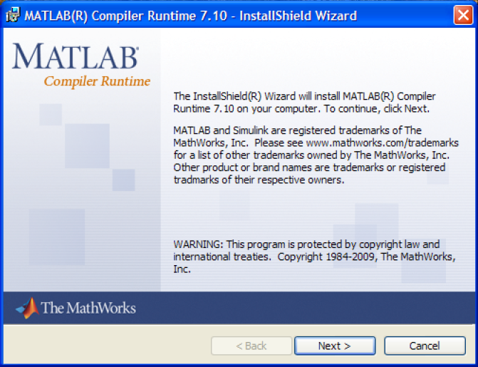
Click the “Install” button and follow the instructions.
Enter in the desired “User Name” and “Organization”, then click “Next”.
The default location where MCR is saved is shown. The user can select a different path by clicking on “Change”; this should typically not be done. Click on the “Next” button.
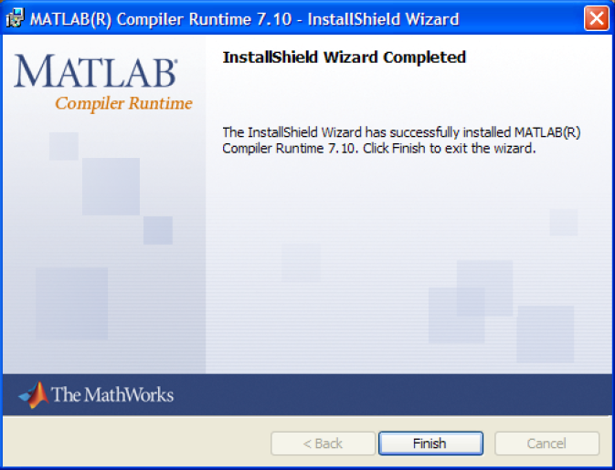
The process may take several minutes. Click “Finish” on the last screen.
This completes the installation of the MATLAB® Compiler Runtime 7.10 components.
Now to install the WTGMV tool simply copy the files “WTGMV.exe”, “SolParm.dat”, “WT3_Model.pdf”, “WT4_Model.pdf” and “WTGMV_Manual.pdf” into any folder on your computer where you wish to run the program. Double click on “WTGMV.exe” to run the program.
IMPORTANT NOTE: In some cases, when the MATLAB® MCR is re-installed on a computer by either removing the older version through the operating system control panel or by removing the older version through the InstallShield Wizard some dll’s may be corrupted and an error message encountered upon running WTGMV: If you encounter this error message, then unzip the files in the zip file “MCRpatch32.zip” – this file is located in the folder MATLAB_runtime” – and execute the “MCRInstallerPatchA.exe”. This will fix the problem. Do not run this patch unless you encounter this problem.
The WTGMV Software Tool General Program Description


In this section the functionality of the WTGMV software is discussed and demonstrated in a few examples.
WTGMV can be used to fit parameters to and/or validate generic models for type 3 and 4 WTGs. The models are the latest developed under the WECC REMTF. This validation can be achieved based on measured field data from a digital fault recorder (DFR) or phasor measurement unit (PMU) at the location of the WTG, or factory test data. It is assumed that the data is either from a fault/voltage-depression event on the grid – in Europe such voltage dips are actually imposed through an IEC testing requirement – or such a test performed on the unit in the factory.
The steps in the typical parameter derivation process, using WTGMV are as follows:
- Extract the recorded response of the device from the DFR or PMU
- Prepare the data in the format expected by WTGMV
- Import the data into WTGMV and also enter an initial estimate of the parameters together with appropriate upper and lower bounds for those parameters that are optimized (a limited number of parameters).
- Run WTGMV to validate/optimize the model parameters.
The process used for model validation is similar to that developed by EPRI for the PPPD tool.[3][4] That is, one of the measured quantities, in this case measured voltage at the WTG terminals is played back into the model while the tool then tries to fit the response of the simulation to the other measure quantities, the real and reactive power output on the unit. For the purposes of the present version of the tool the terminals of the WTG is assumed to be the low-voltage side of the WTG step-up transformer, since the transformer is not modeled.
Data Entry
The user must enter two sets of data into WTGMV. The first step is to choose the appropriate model, i.e. either type 3 or 4 WTG. Once the appropriate model is chosen the data entry and expected format is as explained in the next section.
The data that is of use for the purposes of model validation and parameter estimation using WTGMV is that recorded at the terminals of the WTG (i.e. low-voltage side of the WTG step-up transformer) using a digital fault recorder (DFR), phasor measurement unit (PMU) or similar device. The data needed is the voltage magnitude and the real and reactive power generated by the device. A sampling rate of at least 30 to 60 samples per second is required. Also, the preferred event is a voltage dip or fault that results in at least 10 % or more voltage drop at the WTG. Furthermore, given the highly sophisticated response of these units, to truly validate the model data is needed for multiple levels of voltage dip and at least two different operating conditions (e.g. full-load or near full-load and partial-load). One way such data is obtained in Europe is through field or factory tests.[2]
The only step in preparing the data is to extract the data from the DFR and to convert it to ASCII format (see next section for the exact format). The data may also need to be per unitized.
If the data to be used is from a PMU, then typically what is recorded is the voltage magnitude and angle at the WTG bus. From these quantities the real and reactive power can be calculated.
Examples of Actual Model Validation Achieved with WTGMV
Here we provide several examples of model validation using WTGMV on data from a few different WTG installations. The data was provided under non-disclosure agreements with the vendors.[2]
Note: all the examples here are for illustrative purposes, they do not necessarily represent the best or most suitable fit for each unit. Furthermore, what is shown is the response of specific units at specific installations in Europe designed for specific country grid codes in those markets. The actual response of the equipment can be tuned/designed by the vendors to meet many different requirements for many different grid codes. As such, what is shown here should not be interpreted as the only possible response characteristic of a particular design.
Note: all the examples shown here were run on WTGMV Version 1.0.
Running WTGMV, Menu Selection and Program Usage


To start WTGMV, simply double click on the executable file “WTGMV.exe”. In addition to the actual program a second window will also appear on the screen. The black window is a dialogue window where progress logs of simulations etc. appear. The user has no real interaction with this window. It can be minimized during running of WTGMV or left open to be able to see progress of for example simulation iterations during a run.
On the main program screen, one can see six (6) buttons to click on with the mouse:
- Type 3 – click on this button to go to the type 3 WTG data entry screen to be used for parameter derivation for this model.
- Type 4 – click on this button to go to the type 4 WTG data entry screen to be used for parameter derivation for this model.
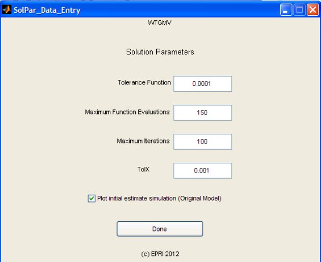
- Solution Parameters – click on this button to change the various solution parameters for the optimization algorithm.
- Manual – clicking this button will bring up the user’s manual documentation (this document).
- About WTGMV – clicking on this button displays some basic information about the tool.
- Quit Program – click on this button to close the program.
Type 3 WTG


Clicking on the “Type 3” button leads the user to the “Type 3 WTG data entry menu”:
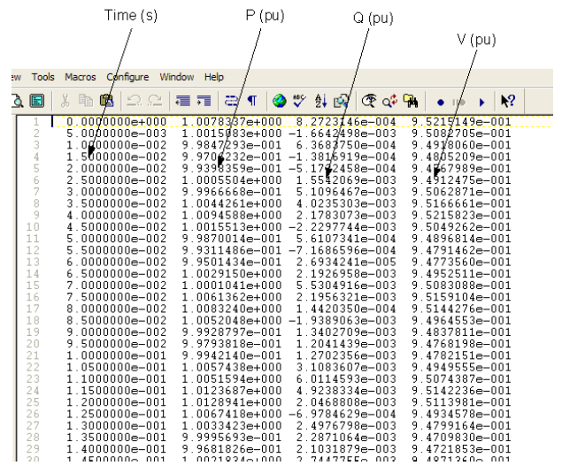
At the top of the window are three text boxes for entering the name of the “Input File”, “Output File” and “Parameter File”, respectively. These file names must not be the same, otherwise the data output from WTGMV may overwrite your input file. The names may be entered by simply clicking in the text boxes, one at a time, and typing the name. The input file is the on-line disturbance measurement data that the user wishes to use to derive the model parameters. The format of the input file depends on the model. For the Type 3 WTG model the expected format of the input file is as follows:
- The file must be a text file.
- It must contain four (4) columns of numeric data. Data in each column must be separated by spaces or tabs.
- There must not be any interruption in the columns of data, e.g. empty lines, lines containing headers, characters etc.
- The first column is assumed to be time. The data MUST BE presented at a fixed sampling rate. That is, the time interval between subsequent data points MUST be constant.
- The second column is assumed to be the magnitude, at each time step, of the WTG real power (P) output in per unit.
- The third column is assumed to be the magnitude of the WTG reactive power (Q) output in per unit.
- The fourth column is assumed to be the magnitude of the WTG terminal voltage in per unit.
All these quantities are as measured at the low-voltage side of the WTG step-up transformer.
An example of an input file is as follows:
The output file generated by WTGMV is a simple text file that contains the results of the simulation process, together with the name of the input file and other pertinent information.
The parameter file is an optional entry. The parameter file name MUST NOT contain an extension, e.g. “parm.txt” is not acceptable, but “parm” is. The parameter file is used to store and reload the on-screen parameter entries. After the parameters are entered by the user by clicking on the button “Save Parameters” this will save the settings and parameters in the file specified in the “Save parameter filename” field for future use. If one then exits the program (by pressing “Quit Program”) or just exist the data entry form (by pressing “Main Menu”), then the next time the user enters the Type 3 WTG data entry page one can reload the parameter settings from the previous session. This is done by re-entering the name of the file in the parameter file text box and then pressing the “Load Parameters” button. The purpose of this feature is to allow the user to store the initial conditions and initial parameter estimates and bounds for use in future sessions.
WARNING: this save and load feature works for each data entry page separately, that is the user cannot save parameters for the Type 3 WTG data entry page and then reload them on the Type 4 WTG data entry page, and vice versa. This is because each of the models and data entry pages is unique.
Most of the parameters of the model are to be simply entered and are not optimized. This is because most of these parameters pertain to settings of the control structure (e.g. flags for various control strategy options) and non-linearities (e.g. deadband settings if used, etc.) and thus do not lend themselves easily to parameter optimization.
All the parameters are assumed to be per unitized on the rating of the unit, as well as the input data.
Now WTGMV is ready to perform the model validation. There are two simulation options:
- Pressing the “Run No Optimize” button simply performs a simulation with the model parameters as entered without trying to optimize them.
- Pressing the “Run and Optimize: button performs the simulation while trying to optimize some of the controller gains and shaft parameters.
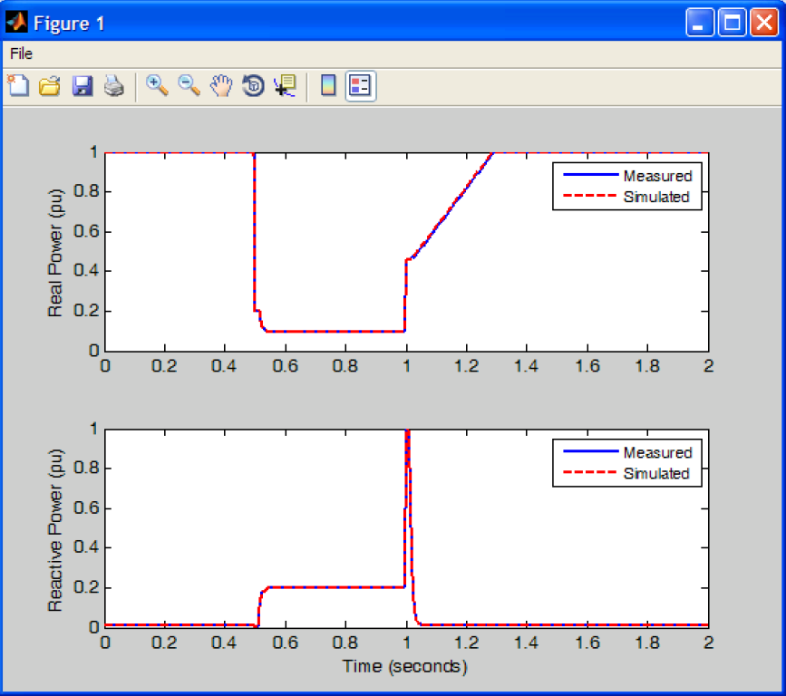
A statement appears in the black dialogue window saying “Please Wait While Processing”. During the simulation, the iterations of the optimization process scroll up on the black dialogue window when performing optimization. Once the simulation is finished a figure is created showing the results of the optimization process. Also, the output file is created with the estimate parameters provided in that file. Also, if the user clicks on the “Output Time Series” check box, the time series of the simulated P and Q is exported and appended at the end of the text file.
The plot output from WTGMV may be saved, printed or copied using the standard Windows functions. For example, click on File -> Save As. As shown the simulation results plotted are both for the “Original” (black dotted line) and “Optimized” (red dotted line) simulation. That is, WTGMV shows the user the simulated fit for the case using the original initial parameter estimates as compared to the simulated results after optimization. The user can turn this feature on or off by going to the “Main Menu”, clicking on the “Solution Parameters” button, and then checking or un-checking the “Plot initial estimate solution (Original Model)” check-box.
To end the parameter derivation work, click on the “Main Menu” button to return to the main screen of WTGMV or on “Quit Program” to quit the program.

Note: WTGMV has some basic data checking procedures in-built. For example, if the input file is not found, or does not contain the right number of columns of data, an error message will appear asking the user to fix this problem before proceeding. Similarly, if for example inappropriate data is entered (an initial estimate is outside the upper and lower bounds defined, or the lower bound is larger than the upper bound etc.) again error messages will pop-up on the screen and ask the user to fix the problem before proceeding. This is true for both models.
Type 4 WTG
For the Type 4 WTG model in general the data entry and options are the same as described above for the Type 3 WTG.
The clear difference between the Type 4 and Type 3 WTG models is that the input parameters are different, since they represent a different type of equipment. The Type 4 model essentially does not include much in terms of modeling the mechanical side of the WTG.
The input file expected is once again an ASCII file with the same format as that described for the Type 3 WTG model.
Tutorial for Using WTGMV


The data presented in this tutorial was generated from a fictitious simulation. It is provided simply for illustrative purposes to show the usage of WTGMV. WTGMV and its underlying algorithm has been extensively tested on actual field recordings from various type 3 and 4 WTGs. Thus, the program has been full demonstrated to work using real life data.
The installation CD has one example files on it that will be used in this tutorial. The file is called “Test.txt” and “Test.mat”. Copy these file to a folder on your computer where you have also copied the WTGMV program.
Now run WTGMV by double clicking on the WTGMV.exe file. Click on the button “Type 4”.
Now let us assume that the file “Test.txt” is the measured response of a WTG. The parameters of the model used to generate this simulation are stored in “Test.mat”
Now in the Type 4 WTG Data Entry screen, enter the name “Test” in the Save Parameter Filename entry and then click the Load Parameters button. Now also enter:
- Input File: Test.txt
- Output File: Test.out (can actually choose any name you wish)
Now click on the “Run no Optimize” button. In the dialogue window you will see the comment “Please Wait While Processing”.
Once the run is finished, you should see a figure appear on the screen that shows the results of the simulation process. A text file called “Test.out” is also created.
Note: If one clicks the “Output Time Series” check box and then clicks on the “Run and Optimize” button again, this time the output file will have appended at the end of it the time series of the simulation results as shown below.
Now let us assume that we had originally typed the data in by hand and wanted to save the current selection of parameters to file for use in a future optimization session. Click on the “Parameter File” text entry box and enter “Test2”. Now click on the “Save Parameters” button.
Now click on “Main Menu” to go back to the main menu. Now if one re-enters the Type 4 WTG data entry sheet and enters “Test2” as the parameter file name and then clicks on the “Load Parameter” button, one should see the stored parameters be re-loaded.
Also, note that while in the Type 4 WTG (and also Type 3) data entry page if one clicks on the button labeled “Block Diagram” the block diagram of the model is displayed in a PDF file.
References
- ↑ EPRI, “Wind Turbine Generator Model Validation (WTGMV) Software User’s Manual (Version 1.0)”, Software Product ID 1024346. [Online]. Available: http://my.epri.com/portal/server.pt?Abstract_id=000000000001024346 .[Accessed June 2014].
- ↑ 2.0 2.1 2.2 Generic Models and Model Validation for Wind and Solar PV Generation: Technical Update EPRI Report, Product ID: 1021763, December 2011 http://my.epri.com/portal/server.pt?Abstract_id=000000000001021763
- ↑ P. Pourbeik, “Automated Parameter Derivation for Power Plant Models Based on Staged Tests”, Proceedings of the IEEE PES Power Systems Conference & Exposition, Seattle, WA, March 2009.
- ↑ P. Pourbeik, “Automated Parameter Derivation for Power Plant Models From System Disturbance Data”, Proceedings of the IEEE PES General Meeting, Calgary, Canada, July 2009.