
Contents
Technical Specifications
The technical specifications for the proposed battery/inverter-based grid simulator for V-27 225-kW wind turbine that will be installed on the DeepCwind floating platform were produced from transient and steady-state modeling described earlier in this report. It was also concluded earlier in this report that other possible grid-simulator solutions (such as a large diesel generator or small diesel genset with synchronous condenser) are not feasible for the application.
The list of technical requirements for various system components that are part of the battery/inverter grid- simulator option is given below:
Batteries
Lithium-based batteries were found to be the best fit in terms of both performance and weight/size limitations. Recommended lithium battery capacity is 50 Ah, based on modeling results. In case of unexpected performance problems, it would be desirable to have capability of accommodating a second parallel string of 50-Ah batteries.
| Technology | Sealed lithium. |
| Nominal battery bank voltage | As required by the inverter. |
| Nominal capacity | Depends on battery type. |
| Maximum continuous charge / discharge current | 300 A |
| Short-term (5 sec) pulse charge / discharge current | 450 A |
| Operating and storage temperature range | -40…..+50°C |
| Minimum battery cut off voltage | Up to bidder to determine. |
| Maximum battery cut off voltage | Up to bidder to determine. |
| Battery arrangement | Circular shelves around the perimeter of the column wall, see platform drawings for details. |
| Maximum weight of a single 50-Ah string | 4400 lbs (including accessories) |
Inverter
| Technology | 3-phase grid forming, 480-VAC voltage source, PWM modulated. |
| Minimum power rating | 300 kVA continuous. |
| Maximum weight | 1800 lbs |
| DC bus voltage range | Up to bidder to determine. |
| DC bus active overvoltage protection | DC chopper desirable. |
| Over current protection (both hardware and software), L-to-G and L-to-L trips | Circuit breakers on both AC and DC sides. |
| Frequency control accuracy | 60 Hz ± 0.1% (±0.01% preferred) |
| Short-term over-current capacity | 150% of full load for 5 sec every 5 min. |
| Enclosure | Force ventilated cabinet. |
| Inverter efficiency at rated load | 97% minimum. |
| Power quality (with filters) | <5% voltage THD. |
| Isolation transformer/ line reactors | Transformer (480 VAC/325 kVA) or line reactors must be designed to comply with IEEE-519 on harmonic current injection (5% TDD max). In case of isolation transformer, a 1800-lbs max weight limit is applied. |
| Voltage imbalance | 1% max. |
| Contingency battery charging | Possibility to charge batteries from an external portable diesel genset. |
Resistive (secondary) load bank
| Power/voltage rating | 300 kVA/480 VAC– delta connected. |
| Maximum load step | 1.5 kW (1kW preferred). |
| Cooling | Force ventilated cabinet. |
| Resistor switching method | Solid-state relays, zero crossing switching. |
| Maximum weight | 1500 lbs. |
| Individual heating elements | Flange-mount tubular elements, salt water/corrosion resistant. |
Main Electrical Panel
| Main 480-AC bus, 600A | Connection point for all equipment: inverter, wind turbine, secondary load, auxiliary transformer and umbilical contingency battery-charging equipment (such as a portable diesel genset for charging the main battery bank). |
| Individual circuit breakers for each component | 500-A molded case circuit breakers for a wind turbine, inverter, secondary load bank and umbilical (all remote trip capable), TBD for auxiliary transformer and portable genset. |
| Enclosure | Industrial panel board cabinet, 1200 lbs. |
| Ground bus | In the case of an isolation transformer, the neutral point of wye winding must be grounded and tied up to the ground bus of the main electrical panel. In case of line reactors, the neutral point of the inverter filter can be the grounding point. |
Supervisory controller
| Secondary load bank control function (based on wind turbine power and battery SOC readings) | Control the secondary load bank to match the wind generation and simultaneous control of battery SOC by adjusting real power flow to/from battery. Maintains the battery SOC at optimum setpoint (TBD by bidder). Max response time of the controller in this mode is a 15 ms. Better response times are highly desirable for better performance and battery longevity. (In fact, this response time is the most critical technical parameter of the grid simulator). |
| Shut down the inverter during periods of no wind to preserve battery SOC (for example, shut down if turbine 10-min average power production is less than 10 kW – both time and kW thresholds must be selectable). Re-start inverter if 10-min average wind speed is greater than 7 m/s (both time and wind speed threshold must be selectable) | Signal from hub anemometer must be provided to the controller. |
| Monitor and log data on all power system components | List of channels TBD. |
| Remote wireless and two-way communication capability | Capability of two-way communication via existing satellite, Ethernet, or cell modem (part of platform DAS), time stamp synchronization capability with platform DAS, capability to send/receive data to/from platform DAS (using TCP/IP based communication protocol). |
| Command inverter to operate in contingency battery charging mode | Charge batteries from external portable diesel genset. |
| Communication with wind turbine controller | Send enable/disable command to wind turbine. |
| Capability to interrupt instrumentation battery charging process during periods of no wind (to preserve main battery state of charge) | Send enable/disable command to secondary charger circuit breaker. |
| Power supply | 24 VDC preferred to match with secondary battery bank nominal voltage. |
One-line Electrical Diagram
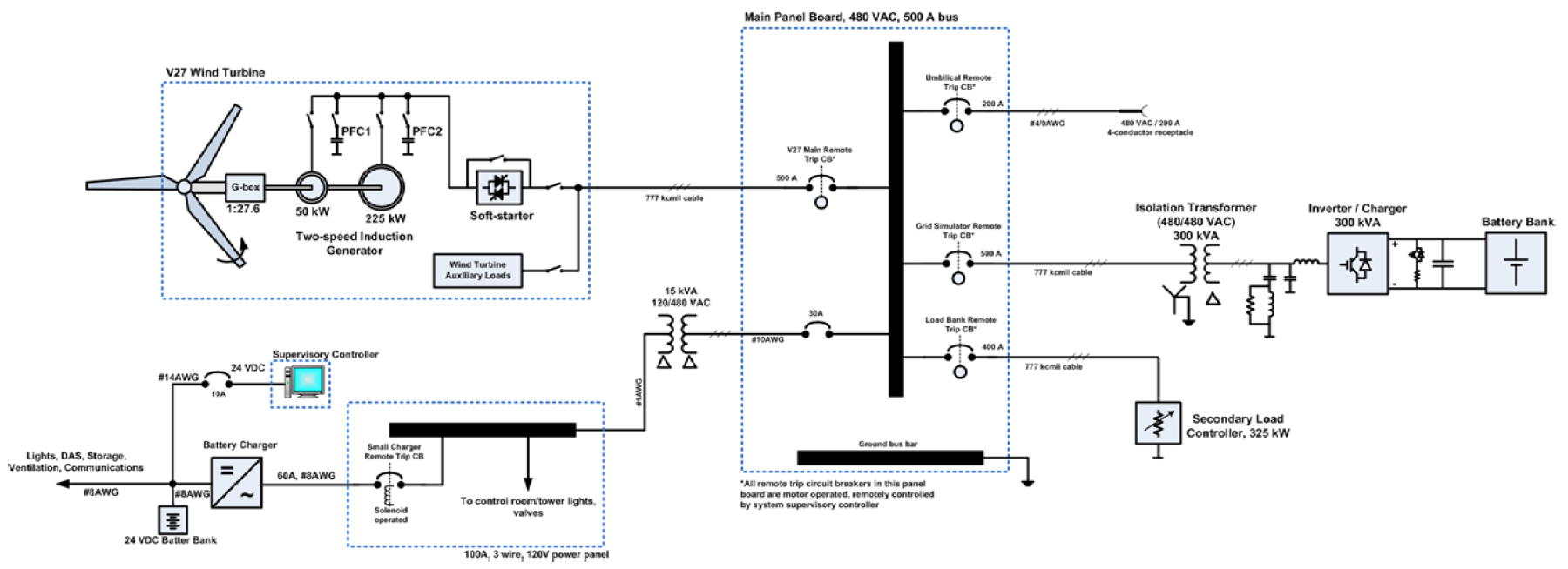
The one-line electrical diagram of proposed battery/inverter-based grid simulator is shown in this section. The main panel board is the point of interconnection of all major system components: V-27 wind turbine, inverter, secondary load, umbilical connection with portable diesel genset, and other platform loads. All these components are protected by the motor-operated remote-trip circuit breakers. All remote-trip circuits are controlled from the system supervisory controller. A choice of 777- kcmil AWG is based on flexible diesel locomotive (DLO) type RHH or RHW cables (777 kcmil allows about 545 A ampacity for three DLO conductors in a conduit at 30°C ambient temperature; correction factors must be applied for higher temperatures). DLO cables are preferred for their flexibility and lighter weights.