
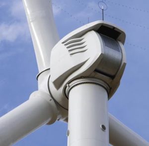
Clipper’s Liberty series is represented by three-blade, upwind, horizontal axis wind turbines with a rated capacity of 2.5-megawatts. Four different models represent the Liberty – 2.5 MW series – C89, C93, C96, and C99.
Liberty is a variable speed wind turbine with a four permanent magnet generators distributed powertrain. The rotor on a Liberty turbine is designed to operate in an upwind configuration at 9.6 to 15.5 revolutions per minute (rpm). The Liberty – 2.5 MW series provides the option of a selectable power factor between 0.95 (overexcited/lagging) and 0.95 (underexcited/leading). For example, by configuring the machine to operate at a slightly overexcited (lagging) power factor, the inverters can compensate for reactive power losses within the wind plant collection system, providing approximately unity power factor operation at the point of interconnection over a wide range of plant output.
 |
|
| Power Regulation | Pitch regulated with variable speed |
|---|---|
| Operating Data | |
| Rated Power | 2500 KW [1] |
| Cut-in wind speed | 4 m/s (9 mph) |
| Cut-out wind speed | 25 m/s (55mph) |
| Wind Class | IEC IA (C89); IEC IIA (C93); IEC IIB (C96); IEC IIIB (C100) |
| Rotor | |
| Rotor diameter | 89 m (292 ft) for the C89, 93 m (305 ft) for the C93, 96 m (315 ft) for the C96 model, and 99 m (325 ft) for the C99 model. |
| Operational interval | 9.6 – 15.5 rpm |
| Towers | |
| Type | Partial Conical – Tubular Steel, 4 Steel Plate Sections |
| Hub heights | 80 m (262 ft)/Other Options Available. |
| Generator | |
| Type | 4 x Synchronous Permanent Magnet (660 kW at 1133 rpm each). |
| Nominal output | 2,500 kW |
| Operational data | 690 VAC +/- 10% Continuous; 690 VAC + 20% for 5 Seconds; 690 VAC + 30% for 0.5 Seconds; 690 VAC – 90% for 3 Seconds; 690 VAC – 100% for 150 Milliseconds. |
Contents
- 1 Vendor Specific Model Characterization
- 2 Parameterization – PSLF Environment
- 3 Results Validation
- 4 Vendor Specific Model Validation
- 5 References
Vendor Specific Model Characterization
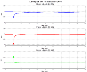
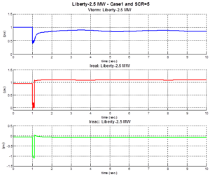
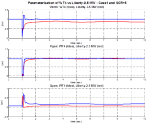
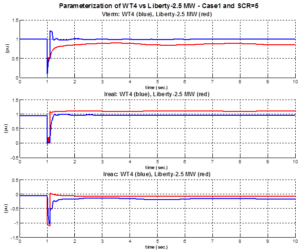
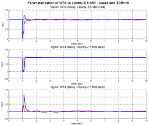
Model Performance: Case 1 – Fault Event
In this case a remote fault is applied to bus 12 for a duration of 6 cycles (0.1 sec).
Liberty-2.5 MW – Case 1 and SCR=5
Liberty-2.5 MW – Case 1 and SCR=10
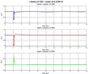
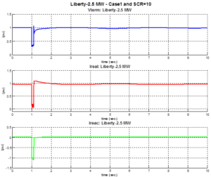
For both SCR settings the reactive current output of the WTG increases during the fault. A current limit of 1.11 pu on the 2.5 MVA machine base is implemented to prevent thermal damage to the converter in the event it was subjected to a short circuit near the terminals of the inverter. After the fault is removed the reactive current returns to its steady state condition.
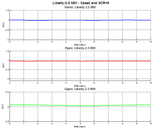
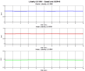
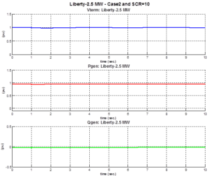
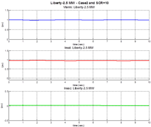
Model Performance: Case 2 – Under-Frequency Event
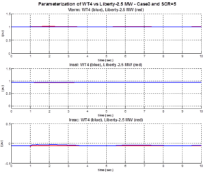
In this case a under frequency event is created by tripping the 100 MVA generation unit at bus 20.
Liberty-2.5 MW – Case 2 and SCR=5
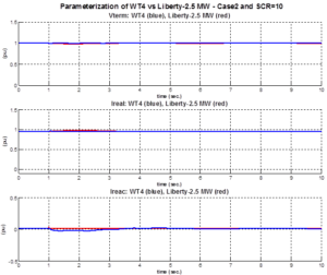
Liberty-2.5 MW – Case 2 and SCR=10
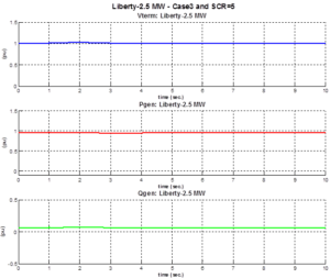
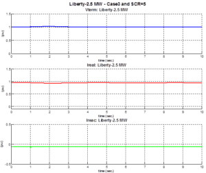
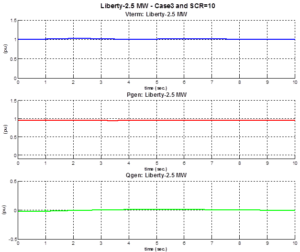
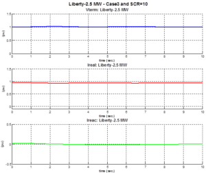
Model Performance: Case 3 – Over-Frequency Event
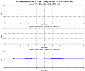
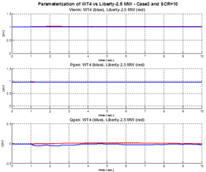
In this case a under frequency event is created by tripping the 100 MVA load at bus 11
Liberty-2.5 MW – Case 3 and SCR=5
Liberty-2.5 MW – Case 3 and SCR=10
Parameterization – PSLF Environment
The parameter values shown in the table resulted from a compromise between the simulated cases (i.e. SCR 5 and SCR 10) and network conditions (i.e. fault, under- and over frequency)
|
There are three generic wind turbine models in PSLF for a type 4 wind turbine (WT4). These models are wt4g, wt4t, and wt4e. The wt4g model includes the generator and converters dynamics. The wt4t model includes the wind aerodynamic model and the wind turbine model. Finally, the wt4e model contains the real and reactive control models. The values for the parameters resulted from a compromise between the two cases (SCR 5 and SCR 10). The set of parameters had to be tuned to satisfactory match the results of dynamic simulation for the VSM and the generic WT4 model for both SCR cases. | |||||||||||||||||||||||||||||||||||||||||||||||||||||||||||||||||||||||||||||||
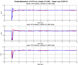
Parameterization: Case 1 – Fault Event
Parameterization of WT4 vs Liberty-2.5 MW – Case 1 and SCR=5
Parameterization of WT4 vs Liberty-2.5 MW – Case 1 and SCR=10
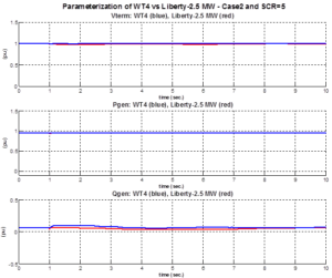
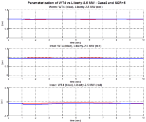
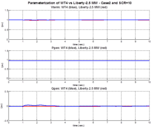
Parameterization: Case 2 – Under-Frequency Event
Parameterization of WT4 vs Liberty-2.5 MW – Case 2 and SCR=5
Parameterization of WT4 vs Liberty-2.5 MW – Case 2 and SCR=10
Parameterization: Case 3 – Over-Frequency Event
Parameterization of WT4 vs Liberty-2.5 MW – Case 3 and SCR=5
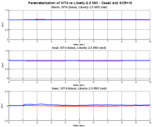
Parameterization of WT4 vs Liberty-2.5 MW – Case 3 and SCR=10
Results Validation
In all figures, the response of the generic model matches the response of the VSM in the While the parameterization, for the individual cases, can be mostly done with satisfactory results, a universal set of parameters, to cover all cases, is hard to find (if at all). For cases 1 and 2 (SCR=10) and case 3 (SCR=5) the generic model matches the response of the VSM in the frequency range of interest. Thus, for these cases the PSLF model is an appropriate representation of the Liberty – 2.5 MW WTG’s behavior for fundamental frequency analysis. However, for all remaining cases and system conditions (i.e. SCR=5 and SCR=10) the generic model does not match the behavior of the VSM.
Vendor Specific Model Validation
No data available