Wind turbines are just one (albeit an important) component of bulk wind plants. With individual turbine sizes now exceeding 1 MW, nameplate ratings for single wind plants of many tens to hundreds of MW are common. The geographic extent of the wind plant must be large enough to not only accommodate the dozens to a hundred or more turbines, but also allow optimal spacing and utilization of local terrain features that will maximize energy production. The infrastructure for connecting a large number of widely distributed turbines to a single point of interconnection with the transmission system has important influence over the electrical characteristics of the wind plant. The installed and proposed utility-scale wind plants in the U.S. have some common design characteristics that offer potential simplifications for constructing aggregated models for transmission system studies. These commonalities stem from practicalities and optimizations regarding the local wind regime, micro-siting of individual turbines, electric system design, and operations and maintenance economies. The result is that, from the power system modeling perspective, large wind plants have the following features in common:
- A single turbine type – Since wind turbines are complex machines that require preventative, predictive, and on-demand maintenance to achieve the highest availability, it is better from a maintenance and operations perspective to utilize the same turbine throughout the wind plant and have a maintenance and operations staff that specializes in all aspects of this single turbine design.
- Medium voltage collector systems and interconnect equipment – The electrical infrastructure which “collects” power generated by each turbine in the plant and delivers it to the transmission system utilizes standard overhead and underground medium voltage (15 to 35 kV) equipment and design practices. Some variations from standard utility practice for medium voltage design are necessary, however, as the operation of wind turbines varies significantly from the distributed end-use loads for which the utility practice is optimized. For example, voltage regulation and protection schemes must be modified to account for generation, rather than load, distributed along the collector lines. The collector lines are an integral part of the wind plant; i.e. they are not utilized to serve non-wind plant load or other electric utility customers.
 Reactive compensation – Maintaining voltages within tolerances at individual turbines within a wind plant while at the same time meeting power factor or voltage regulation requirements at the point of interconnection with the transmission system requires careful management of reactive power. Typical locations for reactive power compensation within a wind plant are 1) at each individual turbine, dependent on the reactive power requirements and characteristics of the rotating machinery in the turbine; 2) at the interconnect substation in the form of switched shunt capacitor banks; and 3) at locations along the medium voltage collector lines depending on the layout of the plant. Some plants have the ability to dynamically control reactive power from each turbine, which offers the possibility of reactive power management for transmission system considerations to be accomplished by the turbines themselves. Terminal voltages at individual turbines, however, may be a constraint on the amount of reactive power that can be delivered to the interconnect substation during periods of high wind generation. In addition, when reactive power is required at the point of interconnection to the transmission network to support voltage, substantial reactive power may be “lost” in the medium voltage collector system between individual wind turbines and the interconnect substation.
- SCADA and Plant Control – Large wind plants typically have fairly extensive means for remote operation of individual turbines and collection of high-resolution operating data. Interfaces to power system operations centers are also being implemented, allowing automated implementation of control area operator commands during certain system conditions – e.g. automatic curtailment.
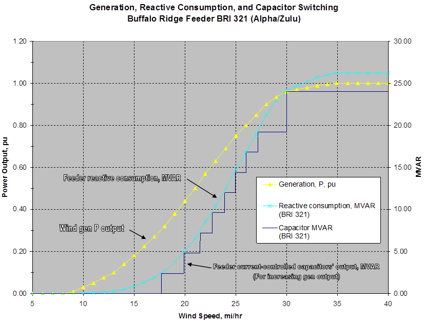
The most important influence of the wind plant infrastructure on the interconnection bus bar characteristics of the wind plant is on the net reactive power capability of the wind plant. Voltage profiles along the collector lines are an internal issue. For purposes of characterizing the plant for transmission studies, the static, dynamic, and load-dependent effects of the collector system on the net reactive power at the interconnection substation must be characterized. Figure on the right illustrates this influence with an example from an operating wind plant. Wind plant generation and net reactive power requirements are shown as functions of wind speed. In the figure, the net reactive power is entirely a function of reactive losses in the lengthy overhead collector lines, since the turbines are assumed to be operating at unity power factor. The stepped line shows how staged shunt capacitor banks on the collector lines might be deployed to account for this load-dependent reactive loss. Not shown on the diagram is how such a scheme would contribute to the dynamic nature of the plant. As wind speeds – and power output – vary, so will the net reactive requirements. Details of the capacitor switching scheme are critical here, since there will be time delays and hysteresis associated with the capacitor bank controls. These parameters must be selected with some knowledge of the time variation of wind generation on the collector line to prevent unnecessary capacitor switching operations and potentially associated voltage flicker.
