
Author: EnerNex[1]
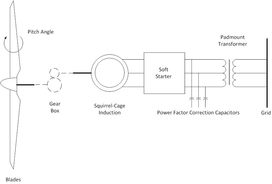
Most wind generators installed at the end of the 20th century were ordinary asynchronous (induction) generators, usually with fixed capacitance to correct for the reactive power demands of that type of generator. An induction generator is essentially an induction motor where the slip is negative, i.e. the rotor speed is slightly ahead of the rotating flux in the stator winding. The induction generator has a squirrel cage rotor which draws magnetizing current from the stator giving rise to a high reactive power demand when fluxing, as when the generator circuit breaker is first closed. Wind turbines with squirrel-cage induction generators connected directly to the line are the simplest electrically. While for purposes of aerodynamic efficiency they operate at nearly constant speed, the slight variation of speed with torque (and power) can significantly reduce mechanical torque transients associated with gusts of wind and grid-side disturbances.
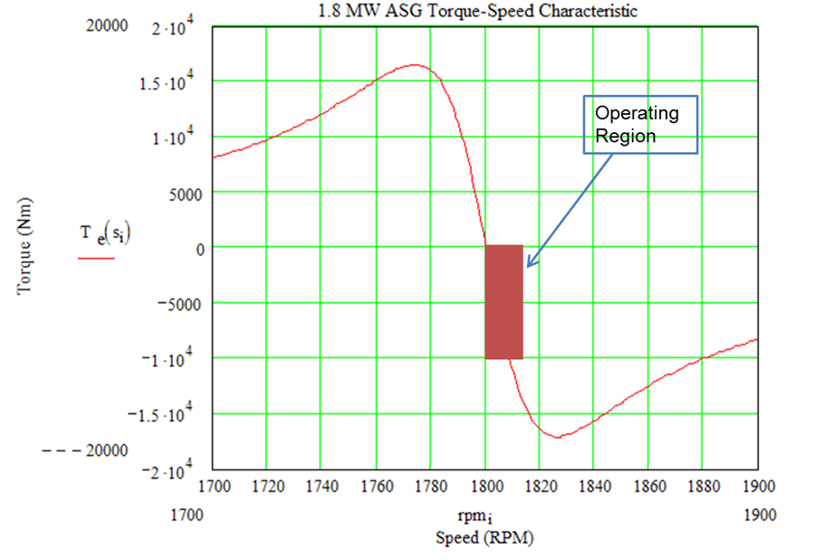
The speed range of the turbine is dictated by the torque vs. speed characteristic of the induction generator. For large generators in today’s commercial turbines, slip at rated torque is less than 1%, which results in very little speed variation over the operating range of the turbine. For a given wind speed, the operating speed of the turbine under steady conditions is a nearly linear function of torque. For sudden changes in wind speed, the mechanical inertia of the drive train will limit the rate of change in electrical output.
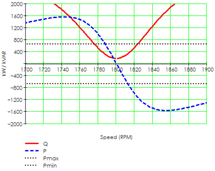
Because the induction generator derives its magnetic excitation from the grid, the response of the turbine during a grid disturbance will be influenced by the extent to which the excitation is disrupted. Figure on the right shows how dramatically the reactive power demand from the network increases as the generator departs from a tight slip regime. For the machine shown, rated slip is about 0.8%, at which point the machine would draw 340 kVAR from a line with rated voltage. If the slip were increased to just 1.0%, the reactive power requirement increases to almost 480 kVAR. At 2.0% slip, reactive power consumption grows to 900 kVAR.
References
- ↑ Documentation, User Support, and Verification of Wind Turbine and Plant Models (DE-EE0001378), September 2012, [Online]. Available: http://www.osti.gov/bridge/servlets/purl/1051403/1051403.pdf. [Accessed May 2013].