Author: EnerNex[1]

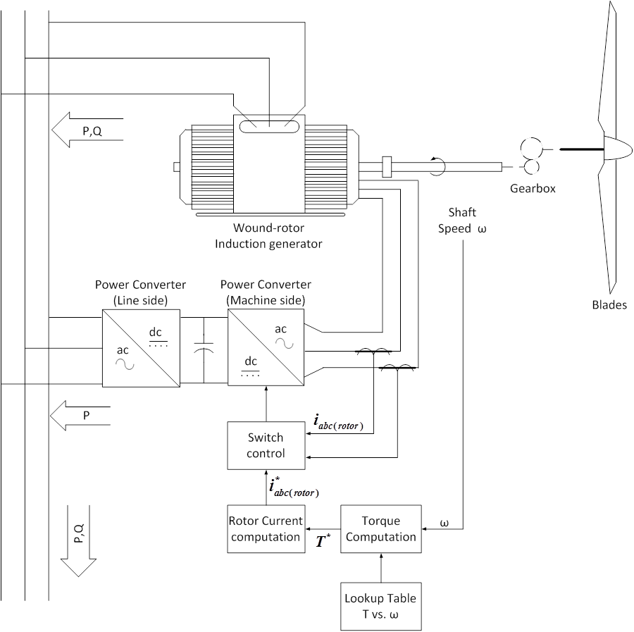
An even more sophisticated rotor current control scheme can be employed in a doubly-fed asynchronous generator as shown in Figure on the right. Here the rotor circuit is supplied with current from a four-quadrant voltage-source, current-regulated power converter. With respect to the grid frequency, such a converter can provide nearly instantaneous regulation of its output currents. Under steady operating conditions, the machine-side converter controls the magnitude and phase of currents in the rotor circuit to achieve desired values of electromagnetic torque. Reactive power flow into the line-connected stator terminals of the generator can also be controlled.

Field-oriented or vector control of induction machines is a well-known technique used in high-performance industrial drive systems, and its application to wind turbines brings similar advantages. In an earlier version of this turbine, the torque command (and therefore the magnitude of the rotor current component responsible for torque production) was linked to the speed of the machine via a “look-up” table. The field-orientation algorithm effectively creates an algebraic relationship between rotor current and torque, and removes the dynamics normally associated with an induction machine. The response of the power converter and control is fast enough to maintain proper alignment of the torque-producing component of the rotor current with the rotor flux so that the machine remains under relative control even during significant grid disturbances.
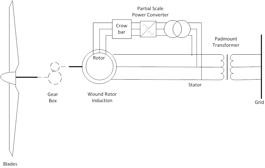
The line-side converter either absorbs or provides real power to the grid, depending on the operating speed of the generator. If the generator is operating below the synchronous speed for the grid frequency and pole number, some amount of real power will flow through the line-side converter to the dc link, then from the machine-side power converter into the rotor circuit. If the turbine is operating above synchronous speed, real power will flow in the opposite direction. The stator is connected to the low voltage side of the wind turbine transformer, but in the case or the DFAG the rotor is a 3-phase coil winding connected to a variable frequency power electronic drive via slip rings rather than an internally short circuited winding. Active power is drawn from the grid to supply the rotor via an AC/DC and DC/AC voltage source converter link and the rotor currents can be completely controlled by the IGBT control circuit. The frequency, which the rotor side converter targets, is that which when superimposed on the rotor speed gives rise to a synchronously rotating field in the air gap.
The active power exchange with the grid is the sum of the power supplied to the grid from the generator stator and the power exchanged with the rotor (minus the converter losses). The stator always exports active power to the grid. The DFAG machine has a number of advantages over the induction generator. Because the rotor frequency is essentially decoupled from the grid it can operate over a wider slip range – 10% to -16% compared to 0% to -2% for an induction generator. The connected DFAG wind turbine is not restricted to a single unique operating speed. This allows the blade tip speed to be varied over a range to better match the wind speed and maintain an efficient operating position for a range of wind speeds. Reactive power is controllable. The initial machine magnetization flux is established from the rotor and the grid side converter still draws only active power. The reactive power is created by the rotor side converter by the firing angle and thus the field angle relative to the rotating field in the stator. The stator similarly appears as a unity power factor device even at starting. Where the turbine control system is required to supply or absorb reactive power, the lead or lag of the rotor field can be controlled by the rotor side converter. Since the synchronous rotor field vectors can be shifted angularly as in the lead and lag of a synchronous machine, the machine can be modeled with direct (d) and quadrature (q) axis components. The phase difference and magnitude of the rotor voltage determine the active and reactive power which is delivered to the terminals of a DFAG. In an ideal device, maximum active power exchange takes place at α = 90° or 270° at which time there is no reactive power exchange. Reactive power exchange is maximized at α = 0° and 180°. The DFAG can therefore manage active and reactive power independently by controls on the grid and rotor side converters. It requires a converter -inverter arrangement, but the maximum expected power through the converter to or from the rotor is about 25% of the total output power of the generator. Therefore the converters are cost effective. There is however a downside to the technology. Under serious system fault conditions the grid voltage may be close to collapse and attempts to meet a target voltage or power factor will drive very high currents into the rotor and hence through the power converters. The converters would be thermally damaged by these currents, so the equipment is generally closely protected by an electronic rotor short circuiting mechanism, often called the “crowbar”. This can be active within 20ms and is followed immediately by a machine trip. Conventional synchronous generators supply reactive energy to the fault and then on fault clearance they participate in the system recovery.
References
- ↑ Documentation, User Support, and Verification of Wind Turbine and Plant Models (DE-EE0001378), September 2012, [Online]. Available: http://www.osti.gov/bridge/servlets/purl/1051403/1051403.pdf. [Accessed May 2013].
