
Author: WECC REMTF[1]
Dynamic representation of large-scale PV plants requires the use of three renewable energy (RE) modules:
- REGC_A – Generator/Converter (inverter) interface with the grid.
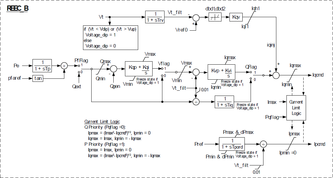
- REEC_B – module, used to represent the Electrical Controls of the inverters. It acts on the active and reactive power reference from the REPC_A module, with feedback of terminal voltage and generator power output, and provides real and reactive current commands to the REGC_A module.
- REPC_A – Plant Controller.
These modules, in addition to others, are also used to represent wind and PV power plants.
The active power control subsystem provides the active current command to the current injection model. The active current command is subject to current limiting, with user-selectable priority between active and reactive current. The active current command is derived from a reference active power and the inverter terminal voltage determined in the network solution. The reference active power is the initial active power from the solved power flow case; or, in the case where a plant controller model (REPC_A) is included, from the plant controller. The reactive power control subsystem provides the reactive current command to the current injection model. The reactive current command is subject to current limiting, with user-selectable priority between active and reactive current. The following reactive power control modes are accommodated:
- Constant power factor, based on the inverter power factor in the solved power flow case
- Constant reactive power, based either on the inverter absolute reactive power in the solved power flow case or, in the case where a plant controller model (REPC_A) is included, from the plant controller.
The option to process the reactive power command via a cascaded set of PI regulators for local reactive power and terminal voltage control, or to bypass these regulators and directly derive a reactive current command from the inverter terminal voltage, shall be provided. In addition, a supplementary, fast-acting reactive current response to abnormally high or low terminal voltages shall be provided.
| REEC_B Input Parameters | ||
|---|---|---|
| Name | Description | Typical Values |
| PFflag | Constant Q (0) or PF (1) local control | – |
| Vflag | Local Q (0) or voltage control (1) | – |
| Qflag | Bypass (0) or engage (1) inner voltage regulator loop | – |
| Pqflag | Priority to reactive current (0) or active current (1) | – |
| Trv | Terminal bus voltage filter time constant (s) | 0.01 to 0.02 |
| Vdip | Low voltage condition trigger voltage (pu) | 0.0 to 0.9 |
| Vup | High voltage condition trigger voltage (pu) | 1.1 to 1.3 |
| Vref0 | Reference voltage for reactive current injection (pu) | 0.95 to 1.05 |
| dbd1 | Overvoltage deadband for reactive current injection (pu) | -0.1 to 0.0 |
| dbd2 | Undervoltage deadband for reactive current injection (pu) | 0.0 to 0.1 |
| Kqv | Reactive current injection gain (pu/pu) | 0.0 to 10.0 |
| Iqhl | Maximum reactive current injection (pu on mbase) | 1.0 to 1.1 |
| Iqll | Minimum reactive current injection (pu on mbase) | -1.1 to -1.0 |
| Tp | Active power filter time constant (s) | 0.01 to 0.02 |
| Qmax | Maximum reactive power when Vflag = 1 (pu on mbase) | – |
| Qmin | Minimum reactive power when Vflag = 1 (pu on mbase) | – |
| Kqp | Local Q regulator proportional gain (pu/pu) | – |
| Kqi | Local Q regulator integral gain (pu/pu-s) | – |
| Vmax | Maximum voltage at inverter terminal bus (pu) | 1.05 to 1.15 |
| Vmin | Minimum voltage at inverter terminal bus (pu) | 0.85 to 0.95 |
| Kvp | Local voltage regulator proportional gain (pu/pu) | – |
| Kvi | Local voltage regulator integral gain (pu/pu-s) | – |
| Tiq | Reactive current regulator lag time constant (s) | 0.01 to 0.02 |
| Tpord | Inverter power order lag time constant (s) | – |
| Pmax | Maximum active power (pu on mbase) | 1.0 |
| Pmin | Minimum active power (pu on mbase) | 0.0 |
| dPmax | Active power up-ramp limit (pu/s on mbase) | – |
| dPmin | Active power down-ramp limit (pu/s on mbase) | – |
| Imax | Maximum apparent current (pu on mbase) | 1.0 to 1.3 |
| REEC_B Internal Variables | ||
| Name | Description | |
| Vt | Raw terminal voltage (pu, from network solution) | |
| Vt_filt | Filtered terminal voltage (pu) | |
| Voltage_dip | Low/high voltage ride-though condition (0 = normal, VRT = 1) | |
| Pe | Inverter active power (pu on mbase) | |
| Pref | Inverter active power reference (pu on mbase, from power flow solution or from plant controller model) | |
| Pfaref | Inverter initial power factor angle (from power flow solution) | |
References
- ↑ WECC REMTF, WECC PV Power Plant Dynamic Modeling Guide, April 2014, [Online]. Available: https://www.wecc.biz/Reliability/WECC%20Solar%20Plant%20Dynamic%20Modeling%20Guidelines.pdf. [Accessed June 2015].