
Author: WECC REMTF[1]
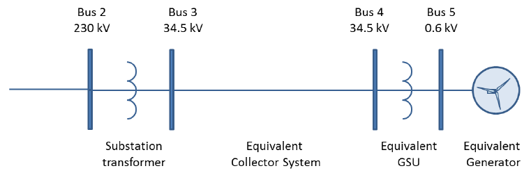
The model call varies according to the software platform. Users must follow the instructions provided with the model documentation, including rules for module call sequence and level of reporting. The two examples correspond to wind power plants with Type 1, Type 2, Type 3 and Type 4 WTGs, represented by the single-generator equivalent system. Model calls for the GE PSLF™, Siemens PTI PSS®E and Power World Simulator platforms are provided. The parameters shown are intended for model testing only, and do not represent the performance of any particular wind power plant or equipment. The following assumptions apply:
- The wind power plant capacity is assumed to be 100 MW.
- Power factor correction capacitors as well as plant-level volt/var devices and controls that may be present are modeled separately.
- For Type 3 and Type 4 WTGs, it is assumed that the plant is rated 110MVA, and that the converters are sized to provide 0.95 leading or lagging power factor at WTG terminals, at rated power and rated voltage.
- For Type 3 and Type 4 WTGs, it is assumed that the plant controls voltage at bus 5.
- The parameters shown are intended for model testing only, and do not represent the performance of any particular wind power plant or equipment.
Contents
GE PSLF™
For a wind power plant with Type 1 WTGs, the function call would be as shown below. The parameters given are for testing purposes only.
| wt1g 5 “Test” 0.6 “1 ” : #1 mva = 110. “Ls” 3.93 “Lp” 0.1773 “Ra” 0. “Tpo” 0.846 “Se1” 0.03 “Se2” 0.179 “Acc” 0.5 “Lpp” 0. “Ll” 0.1 “Tppo” 0. “ndelt” 10 “wdelt” 0.8 wt1t 5 “Test” 0.6 “1 ” : #1 mvacap = 100. “H” 5.30 “D” 0. “Htfrac” 0.92 “Freq1” 5. “Dshaft” 1. wt1p 5 “Test” 0.6 “1 ” : “Tpe” 0.1 “Kdroop” 0.015 “Kp” 0.1 “Ki” 66.667 “Pimax” 1. “Pimin” 0.25 “T1” 0.1 “T2” 0.1 “Kw” 1. |
For a wind power plant with Type 2 WTGs, the same modules mentioned above would be used, in addition to the excitation module. The parameters given are for testing purposes only.
| wt2g 5 “Test” 0.6 “1 ” : #1 mva = 110. “Ls” 6.97 “Lp” 0.301 “Ra” 0.004 “Tpo” 4.23 “Se1” 0.03 “Se2” 0.29 “Acc” 0. “Lpp” 0. “Ll” 0.1 “Tppo” 0. “ndelt” 10 “wdelt” 0.8 wt2t 5 “Test” 0.6 “1 ” : #1 mvacap = 110. “H” 3.46 “D” 0. “Htfrac” 0.81 “Freq1” 1.5 “Dshaft” 0.3 wt2p 5 “Test” 0.6 “1 ” : “Tpe” 0.1 “Kdroop” 0.015 “Kp” 20. “Ki” 1. “Pimax” 1. “Pimin” 0.25 “T1” 0.1 “T2” 0.1 “Kw” 1. wt2e 5 “Test” 0.6 “1 ” : Tw” 0.05 “Kw” 1. “Tp” 0.05 “Kp” 1.00 “Kpp” 0.01 “Kip” 0.01 “Rmax” 0.0977 “Rmin” 0.0061 “Slip1” 0. “Slip2” 0.0054 “Slip3” 0.02 “Slip4” 0.04 “Slip5” 0.1 “Powr1” 0. “Powr2” 0.0217 “Powr3” 0.8988 “Powr4” 0.9 “Powr5” 0.905 |
For a wind power plant with Type 3 WTGs, the function call would as shown below. The parameters given are for testing purposes only.
| regc_a 5 “Test” 0.6 “1 ” : #1 mva=111. “lvplsw” 1. “rrpwr” 10. “brkpt” 0.9 “zerox” 0.5 “lvpl1” 1.22 “vtmax” 1.2 “lvpnt1” 0.8 “lvpnt0” 0.4 “qlim” -1.3 “accel” 0.7 “tg” 0.02 “tfltr” 0.02 “iqrmax” 99. “iqrmin” -99. “xe” 0.8 reec_a 5 “Test” 0.6 “1 ” : #1 “mvab” 0. “vdip” -99. “vup” 99.0 “trv” 0. “dbd1” -0.05 “dbd2” 0.05 “kqv” 0. “iqh1” 1.05 “iql1” -1.05 “vref0” 0. “iqfrz” 0.15 “thld” 0. “thld2” 0. “tp” 0.05 “qmax” 0.436 “qmin” -0.436 “vmax” 1.1 “vmin” 0.9 “kqp” 0. “kqi” 0.1 “kvp” 0. “kvi” 40. “vref1” 0. “tiq” 0.02 “dpmax” 99. “dpmin” -99. “pmax” 1. “pmin” 0. “imax” 1.82 “tpord” 0.02 “pfflag” 0. “vflag” 1. “qflag” 1. “pflag” 0. “pqflag” 0. “vq1” -1. “iq1” 1.45 “vq2” 2. “iq2” 1.45 “vq3” 0. “iq3” 0. “vq4” 0. “iq4” 0. “vp1” -1. “ip1” 1.1 “vp2” 2. “ip2” 1.1 “vp3” 0. “ip3” 0. “vp4” 0. “ip4” 0. wtgq_a 5 “Test” 0.6 “1 ” : #1 “mvab” 111. “kip” 1.5 “kpp” 2.5 “tp” 0.05 “twref” 60. “temax” 1.1 “temin” 0. “p1” 0.15 “spd1” 0.85 “p2” 0.23 “spd2” 0.95 “p3” 0.35 “spd3” 1.1 “p4” 0.46 “spd4” 1.2 “tflag” 0. wtgt_a 5 “Test” 0.6 “1 ” : #1 “mvab” 100. “ht” 4.94 “hg” 0. “dshaft” 1.5 “kshaft” -0.077 “wo” 1. wtga_a 5 “Test” 0.6 “1 ” : #1 “mvab” 100. “ka” 0.007 “theta0” 0. wtgp_a 5 “Test” 0.6 “1 ” : #1 “mvab” 100. “kiw” 25. “kpw” 150. “kic” 30. “kpc” 3. “kcc” 1. “tpi” 0.3 “pimax” 27. “pimin” 0. “piratmx” 10. “piratmn” -10. repc_a 5 “Test” 0.6 “1 “: #1 “mvab” 0. “tfltr” 0.02 “kp” 18. “ki” 5. “tft” 0. “tfv” 0.05 “refflg” 1. “vfrz” 0. “rc” 0. “xc” 0. “kc” 0.02 “vcmpflg” 1. “emax” 0.1 “emin” -0.1 “dbd” 0. “qmax” 0.436 “qmin” -0.436 “kpg” 0.1 “kig” 0.05 “tp” 0.25 “fdbd1” 0. “fdbd2” 0. “femax” 99. “femin” -99. “pmax” 99. “pmin” -99. “tlag” 0.1 “ddn” 20. “dup” 0. “frqflg” 0. |
For a wind power plant with Type 4 WTGs, the function call would as shown below. The parameters given are for testing purposes only.
| regc_a 5 “Test” 0.6 “1 ” : #1 mva=111. “lvplsw” 1. “rrpwr” 10. “brkpt” 0.9 “zerox” 0.5 “lvpl1” 1.22 “vtmax” 1.2 “lvpnt1” 0.8 “lvpnt0” 0.4 “qlim” -1.3 “accel” 0.7 “tg” 0.02 “tfltr” 0.02 “iqrmax” 9999. “iqrmin” -999. “xe” 0.8 reec_a 5 “Test” 0.6 “1 ” : #1 “mvab” 0. “vdip” -99. “vup” 99.0 “trv” 0. “dbd1” -0.05 “dbd2” 0.05 “kqv” 0. “iqh1” 1.05 “iql1” -1.05 “vref0” 0. “iqfrz” 0.15 “thld” 0. “thld2” 0. “tp” 0.05 “qmax” 0.436 “qmin” -0.436 “vmax” 1.1 “vmin” 0.9 “kqp” 0. “kqi” 0.1 “kvp” 0. “kvi” 40. “vref1” 0. “tiq” 0.02 “dpmax” 99. “dpmin” -99. “pmax” 1. “pmin” 0. “imax” 1.82 “tpord” 0.02 “pfflag” 0. “vflag” 1. “qflag” 1. “pflag” 0. “pqflag” 0. “vq1” -1. “iq1” 1.45 “vq2” 2. “iq2” 1.45 “vq3” 0. “iq3” 0. “vq4” 0. “iq4” 0. “vp1” -1. “ip1” 1.1 “vp2” 2. “ip2” 1.1 “vp3” 0. “ip3” 0. “vp4” 0. “ip4” 0. repc_a 5 “Test” 0.6 “1 “: #1 “mvab” 0. “tfltr” 0.02 “kp” 18. “ki” 5. “tft” 0. “tfv” 0.05 “refflg” 1. “vfrz” 0. “rc” 0. “xc” 0. “kc” 0.02 “vcmpflg” 1. “emax” 0.1 “emin” -0.1 “dbd” 0. “qmax” 0.436 “qmin” -0.436 “kpg” 0.1 “kig” 0.05 “tp” 0.25 “fdbd1” 0. “fdbd2” 0. “femax” 99. “femin” -99. “pmax” 99. “pmin” -99. “tlag” 0.1 “ddn” 20. “dup” 0. “frqflg” 0. |
PowerWorld Simulator
For a wind power plant with Type 1 WTGs, the function call would be as shown below. The parameters given are for testing purposes only.
| wt1g 5 “Test” 0.6 “1 ” : #1 mva=110. “Ls” 3.93 “Lp” 0.1773 “Ra” 0. “Tpo” 0.846 “Se1” 0.03 “Se2” 0.179 “Acc” 0.5 “Lpp” 0. “Ll” 0.0 “Tppo” 0. “ndelt” 10 “wdelt” 0.8 wt1t 5 “Test” 0.6 “1 ” : #1 mvacap=100. “H” 5.30 “D” 0. “Htfrac” 0.92 “Freq1” 5. “Dshaft” 1. wt1p 5 “Test” 0.6 “1 ” : “Tpe” 0.1 “Kdroop” 0.015 “Kp” 0.1 “Ki” 66.667 “Pimax” 1. “Pimin” 0.25 “T1” 0.1 “T2” 0.1 “Kw” 1. |
For a wind power plant with Type 2 WTGs, the same modules mentioned above would be used, in addition to the excitation module. The parameters given are for testing purposes only.
| wt2g 5 “Test” 0.6 “1 ” : #1 mva=110. “Ls” 6.97 “Lp” 0.301 “Ll” 0.1 “Ra” 0.004 “Tpo” 4.23 “Se1” 0.03 “Se2” 0.29 “Spdrot” 1.04 “Acc” 0. wt2t 5 “Test” 0.6 “1 ” : #1 mvacap=110. “H” 3.46 “D” 0. “Htfrac” 0.81 “Freq1” 1.5 “Dshaft” 0.3 wt2p 5 “Test” 0.6 “1 ” : “Tpe” 0.1 “Kdroop” 0.015 “Kp” 20. “Ki” 1. “Pimax” 1. “Pimin” 0.25 “T1” 0.1 “T2” 0.1 “Kw” 1 wt2e 5 “Test” 0.6 “1 ” : “Tw” 0.05 “Kw” 1. “Tp” 0.05 “Kp” 1.00 “Kpp” 0.01 “Kip” 0.01 “Rmax” 0.0977 “Rmin” 0.0061 “Slip1” 0. “Slip2” 0.0054 “Slip3” 0.02 “Slip4” 0.04 “Slip5” 0.1 “Powr1” 0. “Powr2” 0.0217 “Powr3” 0.8988 “Powr4” 0.9 “Powr5” 0.905 |
For a wind power plant with Type 3 WTGs, the function call would as shown below. The parameters given are for testing purposes only.
| regc_a 5 “Test” 0.6 “1 ” : #1 mva=111. “lvplsw” 1. “rrpwr” 10. “brkpt” 0.9 “zerox” 0.5 “lvpl1” 1.22 “vtmax” 1.2 “lvpnt1” 0.8 “lvpnt0” 0.4 “qlim” -1.3 “accel” 0.7 “tg” 0.02 “tfltr” 0.02 “iqrmax” 99. “iqrmin” -99. “xe” 0.8 reec_a 5 “Test” 0.6 “1 ” : #1 “mvab” 0. “vdip” -99. “vup” 99.0 “trv” 0. “dbd1” -0.05 “dbd2” 0.05 “kqv” 0. “iqh1” 1.05 “iql1” -1.05 “vref0” 0. “iqfrz” 0.15 “thld” 0. “thld2” 0. “tp” 0.05 “qmax” 0.436 “qmin” -0.436 “vmax” 1.1 “vmin” 0.9 “kqp” 0. “kqi” 0.1 “kvp” 0. “kvi” 40. “vref1” 0. “tiq” 0.02 “dpmax” 99. “dpmin” -99. “pmax” 1. “pmin” 0. “imax” 1.82 “tpord” 0.02 “pfflag” 0. “vflag” 1. “qflag” 1. “pflag” 0. “pqflag” 0. “vq1” -1. “iq1” 1.45 “vq2” 2. “iq2” 1.45 “vq3” 0. “iq3” 0. “vq4” 0. “iq4” 0. “vp1” -1. “ip1” 1.1 “vp2” 2. “ip2” 1.1 “vp3” 0. “ip3” 0. “vp4” 0. “ip4” 0. wtgq_a 5 “Test” 0.6 “1 ” : #1 “mvab” 111. “kip” 1.5 “kpp” 2.5 “tp” 0.05 “twref” 60. “temax” 1.1 “temin” 0. “p1” 0.15 “spd1” 0.85 “p2” 0.23 “spd2” 0.95 “p3” 0.35 “spd3” 1.1 “p4” 0.46 “spd4” 1.2 “tflag” 0. wtgt_a 5 “Test” 0.6 “1 ” : #1 “mvab” 100. “ht” 4.94 “hg” 0. “dshaft” 1.5 “kshaft” -0.077 “wo” 1. wtga_a 5 “Test” 0.6 “1 ” : #1 “mvab” 100. “ka” 0.007 “theta0” 0. wtgp_a 5 “Test” 0.6 “1 ” : #1 “mvab” 100. “kiw” 25. “kpw” 150. “kic” 30. “kpc” 3. “kcc” 1. “tpi” 0.3 “pimax” 27. “pimin” 0. “piratmx” 10. “piratmn” -10. repc_a 5 “Test” 0.6 “1 ” : #1 “mvab” 0. “tfltr” 0.02 “kp” 18. “ki” 5. “tft” 0. “tfv” 0.05 “refflg” 1. “vfrz” 0. “rc” 0. “xc” 0. “kc” 0.02 “vcmpflg” 1. “emax” 0.1 “emin” -0.1 “dbd” 0. “qmax” 0.436 “qmin” -0.436 “kpg” 0.1 “kig” 0.05 “tp” 0.25 “fdbd1” 0. “fdbd2” 0. “femax” 99. “femin” -99. “pmax” 99. “pmin” -99. “tlag” 0.1 “ddn” 20. “dup” 0. “frqflg” 0. |
For a wind power plant with Type 4 WTGs, the function call would as shown below. The parameters given are for testing purposes only.
| regc_a 5 “Test” 0.6 “1 ” : #1 mva=111. “lvplsw” 1. “rrpwr” 10. “brkpt” 0.9 “zerox” 0.5 “lvpl1” 1.22 “vtmax” 1.2 “lvpnt1” 0.8 “lvpnt0” 0.4 “qlim” -1.3 “accel” 0.7 “tg” 0.02 “tfltr” 0.02 “iqrmax” 9999. “iqrmin” -999. “xe” 0.8 reec_a 5 “Test” 0.6 “1 ” : #1 “mvab” 0. “vdip” -99. “vup” 99.0 “trv” 0. “dbd1” -0.05 “dbd2” 0.05 “kqv” 0. “iqh1” 1.05 “iql1” -1.05 “vref0” 0. “iqfrz” 0.15 “thld” 0. “thld2” 0. “tp” 0.05 “qmax” 0.436 “qmin” -0.436 “vmax” 1.1 “vmin” 0.9 “kqp” 0. “kqi” 0.1 “kvp” 0. “kvi” 40. “vref1” 0. “tiq” 0.02 “dpmax” 99. “dpmin” -99. “pmax” 1. “pmin” 0. “imax” 1.82 “tpord” 0.02 “pfflag” 0. “vflag” 1. “qflag” 1. “pflag” 0. “pqflag” 0. “vq1” -1. “iq1” 1.45 “vq2” 2. “iq2” 1.45 “vq3” 0. “iq3” 0. “vq4” 0. “iq4” 0. “vp1” -1. “ip1” 1.1 “vp2” 2. “ip2” 1.1 “vp3” 0. “ip3” 0. “vp4” 0. “ip4” 0. repc_a 5 “Test” 0.6 “1 “: #1 “mvab” 0. “tfltr” 0.02 “kp” 18. “ki” 5. “tft” 0. “tfv” 0.05 “refflg” 1. “vfrz” 0. “rc” 0. “xc” 0. “kc” 0.02 “vcmpflg” 1. “emax” 0.1 “emin” -0.1 “dbd” 0. “qmax” 0.436 “qmin” -0.436 “kpg” 0.1 “kig” 0.05 “tp” 0.25 “fdbd1” 0. “fdbd2” 0. “femax” 99. “femin” -99. “pmax” 99. “pmin” -99. “tlag” 0.1 “ddn” 20. “dup” 0. “frqflg” 0. |
Siemens PTI PSS®E
For a wind power plant with Type 1 WTGs, the function call would be as shown below. The parameters given are for testing purposes only.
| 5 ‘WT1G1’ 1 0.84600 0.0000 3.9270 0.17730 0.0000 0.10000 1.0000 0.30000E-01 1.2000 0.17900 / 5 ‘WT12T1’ 1 5.3000 0.0000 0.91800 5.0000 1.0000 / 5 ‘WT12A1’ 1 0.1500E-01 0.1000 0.1500E-01 0.1000 0.1000 0.1000 0.9000 0.2500 / |
For a wind power plant with Type 2 WTGs, the same modules mentioned above would be used, in addition to the excitation module. The parameters given are for testing purposes only.
| 5 ‘ WT2G1’ 1 0.12602 6.8399 0.18084 0.44190E-02 0.10994 1.0000 0.0000 1.2000 0.0000 0.0000 0.21700E-01 0.89880 0.90000 0.90500 0.0000 0.54000E-02 0.20000E-01 0.40000E-01 0.10000 / 5 ‘ WT2E1’ 1 0.5000E-01 0.5000E-01 1.000 1.000 0.9900 0.5000E-01 / 5 ‘ WT12T1’ 1 3.4600 0.0000 0.81000 1.5000 0.30000 / 5 ‘ WT12A1’ 1 0.1500E-01 20.00 1.000 .1000 .1000 .1000 1.000 .2500 / |
For a wind power plant with Type 3 WTGs, the function call would as shown below. The parameters given are for testing purposes only.
| 5 ‘USRMDL’ 1 ‘REGCAU1’ 101 1 1 14 3 4 1 0.20000E-01 10.000 0.90000 0.40000 1.2200 1.2000 0.80000 0.40000 -1.3000 0.20000E-01 0.70000 999.00 -999.00 1.0000 / ”’5 ‘USRMDL’ 1 ‘REECAU1′ 102 0 6 45 6 9 5 0 1 1 0 0 -99.00 99.00000 0.20E-01 0.000000 0.000000 0.0000 99.00000 -99.0000 0.000000 0.150000 0.0000 0.000000 0.50E-01 0.436000 -0.43600 1.1000 0.900000 0.000000 0.100000 0.000000 40.000 0.000000 0.20E-01 0.450000 -0.45000 1.1200 0.40E-01 1.100000 0.40E-01 0.290000 1.2500 1.330000 0.000000 0.000000 0.000000 0.0000 0.000000 0.000000 1.150000 1.100000 1.2400 2.000000 1.240000 0.000000 0.000000 /”’ 5 ‘USRMDL’ 1 ‘WTDTAU1’ 103 0 0 5 4 3 4.9500 0.0000 0.0000 1.8000 1.5000 / 5 ‘USRMDL’ 1 ‘WTPTAU1’ 104 0 0 10 3 1 25.000 150.00 30.000 3.0000 0.0000 0.30000 27.000 0.0000 10.000 -10.000 / 5 ‘USRMDL’ 1 ‘WTARAU1’ 105 0 0 2 0 1 0.70000E-02 0.0000 / ”’5 ‘USRMDL’ 1 ‘REPCTAU1’ 107 0 7 27 7 9 5 3 2 ‘1’ 1 1 0 0.20000E-01 18.000 5.0000 0.0000 0.15000 -1.0000 0.0000 0.0000 0.0000 999.00 -999.00 0.0000 0.0000 0.43600 -0.43600 0.10000 0.50000E-01 0.25000 0.0000 0.0000 999.00 -999.00 999.00 -999.00 0.10000 20.000 0.0000 /”’ 5 ‘USRMDL’ 1 ‘WTTQAU1’ 505 0 1 15 3 3 0 3.0000 0.60000 0.20000E-01 5.0000 1.2500 0.0000 0.20000 0.69000 0.40000 0.78000 0.60000 0.98000 1.0000 1.2000 100.50 / |
For a wind power plant with Type 4 WTGs, the function call would as shown below. The parameters given are for testing purposes only.
| 5 ‘USRMDL’ 1 ‘REGCAU1’ 101 1 1 14 3 4 1 0.20000E-01 10.000 0.90000 0.40000 1.2200 1.2000 0.80000 0.40000 -1.3000 0.20000E-01 0.70000 999.00 -999.00 1.0000 / ”’5 ‘USRMDL’ 1 ‘REECAU1′ 102 0 6 45 6 9 0 0 1 1 1 0 -99.00 99.000 0.00000000 -0.500E-01 0.50000E-01 0.0000 1.0500 -1.0500000 0.00000000 0.150000000 0.0000 0.0000 0.5000E-01 0.40000000 -0.40000000 1.1000 0.9000 0.00000000 0.10000000 0.000000000 120.00 0.0000 0.2000E-01 99.0000000 -99.0000000 1.0000 0.0000 1.70000000 0.4000E-01 0.290000000 1.2500 1.3300 0.00000000 0.00000000 0.000000000 0.0000 0.0000 0.00000000 1.15000000 1.100000000 1.2400 2.0000 1.24000000 0.00000000 0.000000000 /”’ 5 ‘USRMDL’ 1 ‘WTDTAU1’ 103 0 0 5 4 3 5.3000 0.0000 0.92000 2.1320 1.0000 / ”’5 ‘USRMDL’ 1 ‘REPCAU1’ 107 0 7 27 7 9 0 0 0 ‘0’ 1 1 0 0.20E-01 18.00000 5.0000 0.00000 0.15000 -1.00000 0.000000 0.0000 0.00000 999.000 -999.000 0.000000 0.0000 0.43600 -0.4360 0.100000 0.50E-01 0.2500 0.00000 0.00000 999.0000 -999.000 999.00 -999.00 0.10000 20.00000 0.000000 / |
References
- ↑ WECC REMTF, WECC Wind Power Plant Dynamic Modeling Guide, April 20014, [Online]. Available: https://www.wecc.biz/Reliability/WECC%20Solar%20Plant%20Dynamic%20Modeling%20Guidelines.pdf. [Accessed June 2015].