Author: WECC REMTF[1]

A large amount of PV generation is projected to be installed in the Western Interconnection in the form of distribution-connected commercial or residential installations, and transmission-connected large-scale plants. There is wide consensus that representation of PV systems in large-scale simulations needs to be improved to capture the potential effect on local areas as well as the overall system. The Modeling and Validation Work Group (MVWG) of the Western Electricity Coordinating Council (WECC) recently expanded the scope of its Renewable Energy Modeling Task Force (REMTF) to address modeling of PV systems.
Contents
Brief Background
General Characteristics

_and_general_topology_(right).png)
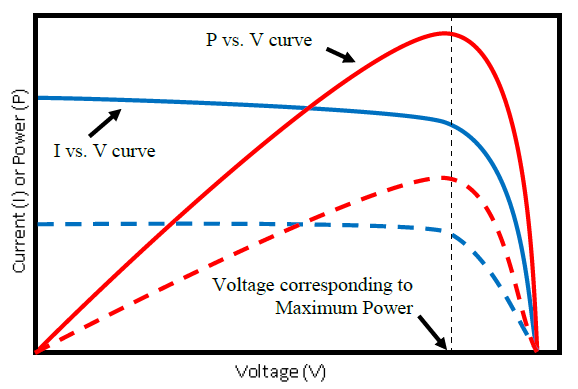
In a PV system, the PV array converts solar radiation directly into direct current (DC) electricity. At a given solar irradiance and cell temperature, the current and power output of the array is a function of terminal voltage. The voltage Vs current characteristic (or IV curve) is nonlinear. There is a voltage level at which maximum power is extracted for a given irradiance level. The available current and power varies in proportion to the effective irradiance incident on the plane of the array. Temperature effects are secondary compared to irradiance, with lower temperature yielding higher performance. Irradiance level, ambient temperature, wind speed affect cell temperature. To maximize energy capture, some PV arrays are mounted on sun-tracking structures.
An inverter is used to couple the PV array to an AC network. One of the control objectives is maximum power tracking, which means that the voltage across the capacitor is controlled such that the PV array operates at the maximum power point. The inverter also regulates ac current magnitude very fast, even during disturbances, to ensure that current and temperature limits of the switching elements in the power block are not exceeded. Inverters also have the capability to change power factor, within the current magnitude limits. With appropriate controls implemented, inverter-based reactive power capability could be used to achieve reactive power control objectives at the plant level. The integrated isolation transformer and filter reduce harmonic injection into the grid. Additional filtering may be applied at the DC side to reduce ripple effects, and at the inverter output to reduce high frequency electromagnetic emissions.
The grid converter monitors the AC voltage and frequency to modulate converter behavior and disconnect the inverter from the grid when voltage and frequency tolerances are exceeded. The IEEE 1547-2003 standard defines voltage and frequency thresholds for residential and commercial PV systems and other distributed energy resources. In addition, IEEE 1547 requires that distribution-connected PV inverters de-energize after faults on the area electric power system (EPS) circuit and prior to circuit reclosure. Inverters must “cease to energize” within 2 seconds of the formation of an electrical island (i.e., when a portion of the grid disconnects from the bulk system). This feature is commonly referred to as “anti-islanding”. PV inverters connected to the customer side of the meter are required to have certification that they comply with these and other safety and grid compatibility requirements. UL 1741 is an example of certification that addresses this issue.
| Voltage Range (% Nominal) | Max, Clearing Time (sec)* |
|---|---|
| V < 50% | 0.016 |
| 50% ≤ V < 88% | 2.0 |
| 110% < V < 120% | 1.0 |
| V ≥ 120% | 0.16 |
| * Maximum clearing times for DER ≤ 30 kW; Default clearing times for DER > 30 kW | |
| Frequency Range (Hz) | Max. Clearing Time (sec) |
| f > 60.5 | 0.16 |
| f < 57.0* | 0.16 |
| 59.8 < f < 57.0** | Adjustable (0.16 and 300) |
| * 59.3 Hz if DER ≤ 30 kW; ** For DER > 30 kW | |
Interconnection standards for central-station PV systems connected directly to the transmission (and sometimes distribution) grid are evolving and can vary considerably from the above. Currently, the NERC Integration of Variable Generation Task Force (IVGTF) is working on recommendations on various aspects of reliability standards applicable to PV and wind generation.
PV Systems
.png)

PV systems are highly modular and can be designed for a wide range of applications, from small residential systems to utility-scale, transmission-connected power plants. Distribution-connected residential and commercial systems typically connect to the customer side of the meter at single phase (120/240V) or three-phase (208/480V). Typical residential systems are less than 10 kW and have a single inverter, while commercial systems can reach several MW and typically have multiple inverters. Power is injected into the grid at unity power factor. Residential and commercial systems are electrically separated from the transmission system by two transformer stages and equivalent line impedance.
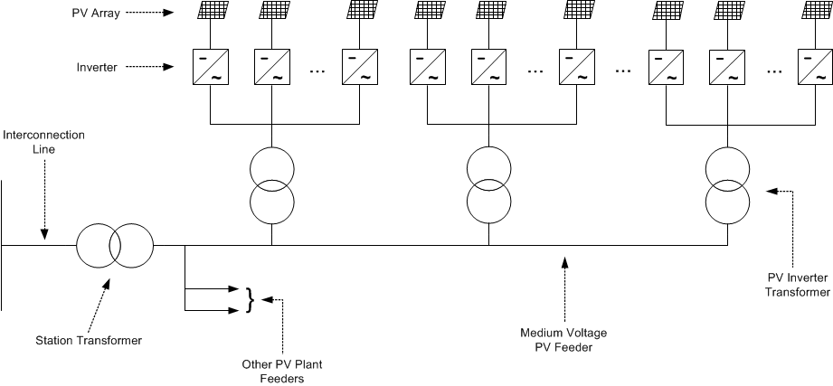
Central-station systems connect to the medium voltage distribution system or transmission system. Presently, the largest central-station PV system presently installed in the US is 300 MW, however, multiple systems of higher capacity are being proposed, and are considered as an integral part of future deployment scenarios. A typical central-station PV plant consists of several individual PV inverters tied to a medium voltage collector system. The nameplate rating of utility-scale inverter range from 100 kVA to 1000 kVA. They operate at low voltage (<600 Vac) output. A step-up transformer connects the inverters to the medium voltage system. Several inverters may be connected to a single pad-mounted transformer. PV plants as large as 14 MW have been connected to directly to an existing distribution feeder, or to the unit station through a dedicated feeder. Larger PV plants would be transmission-connected. The design would consist of a collector system with one or more radial feeders, a dedicated medium voltage station and bulk transformer. An interconnection line would be needed unless the collector system station is adjacent to the interconnection point. Reactive power support at the interconnection point, to the extent that it is required, can be provided by the inverters, dedicated plant-level reactive power support equipment such as mechanically-switched capacitors, or a combination of both.
Energy storage is rarely installed in conjunction with grid-connected PV systems. Therefore, variations in irradiance are reflected into variations of PV plant output. In addition to the predictable seasonal and diurnal cycles, short-term irradiance variability also occurs as a result of cloud shadows moving across the PV array. Variability is a function of cloud characteristics (density, size, velocity, opacity, height) plant size and tracking method and physical separation between individual PV systems. Compared to irradiance measured at a single point, output variability of large PV plant or a collection of distributed PV systems varies much more slowly. Significant work has recently been done in this area.[2]
Applicable Technologies
- PV Plant Architecture
- Types of PV Arrays and Tracking Systems
- Inverters and Other Balance of Systems
Interconnection Procedures
In general, interconnection of new large-scale generating facilities takes place in accordance with the transmission provider’s pro forma Open Access Transmission Tariff (OATT) on file with the FERC. FERC Order 2003 sets forth the Standard LGIP for generators greater than 20 MW as well as the Standard Large Generator Interconnection Agreement (LGIA). These documents lay out the responsibilities of the both the transmission provider and the interconnection customer.
Interconnection Performance Requirements
Existing requirements have for the most part been centered on conventional utility-scale generation plants such as thermal (coal, natural gas, nuclear) and hydro units. Given the growing number of renewable energy generation facilities, a current challenge for the industry is to determine what expectation should be placed on these plants to reliably operate the grid.
- Voltage and Frequency Tolerance
- Frequency Tolerance (Under/Over-Frequency)
- Reactive Power Capability and Volt/VAr Control
- SCADA Integration Requirements
- Station Configuration and Protection
- Current Efforts to Update Interconnection Procedures and Standards
Modeling
Dynamic Simulations – Generic Models
Central Station PV Systems
The WECC Data Preparation Manual states that single generating units 10 MVA or higher, or aggregated capacity of 20 MVA connected to the transmission system (60kV and above) through a step-up transformer(s) should be modeled as distinct generators in WECC base cases.[3] It also states that collector-based system such as wind or solar plants connected to the transmission grid may be represented as an equivalent generator, low voltage to intermediate voltage transformer, equivalent collector circuit, and transformer, as recommended by REMTF’s WECC Wind Power Plant Power Flow Modeling Guide.
Distribution-Connected PV Systems
In some ways, representation of distribution-connected PV systems in bulk system studies is more challenging. In WECC base cases, the distribution system is not typically represented and the load, along with embedded distributed generation, is typically lumped at the transmission level.
References
- ↑ WECC REMTF,WECC Guide for Representation of Photovoltaic Systems In Large-Scale Load Flow Simulations, August 2010, [Online]. Available: https://www.wecc.biz/Reliability/WECC%20PV%20Plant%20Power%20Flow%20Modeling%20Guidelines%20-%20August%202010.pdf. [Accessed June 2015].
- ↑ Mills, et. al., “Understanding Variability and Uncertainty of Photovoltaics for Integration with the Electric Power System”, http://debarel.com/BSB_Library/2009_pv_variability.pdf.
- ↑ WECC Data Preparation Manual For Power Flow Base Cases and Dynamic Stability Data, REV. 7, System Review Work Group, Technical Studies Subcommittee, October 2014. [Online]. Available: https://www.google.com/url?sa=t&rct=j&q=&esrc=s&source=web&cd=2&ved=0CCUQFjAB&url=https%3A%2F%2Fwww.wecc.biz%2FReliability%2FWECC_Data_Preparation_Manual_BCCS_WECC_TECH_Zones.docx&ei=AH-NVcqbIsy1ggSyt6bYBg&usg=AFQjCNHAhbrR47d_w8LvEOdLS8T4O8h2JQ&sig2=xSU4WrOxciQ3YZuMQFh6aA [Accessed June 2015].
