Author: EnerNex[1]
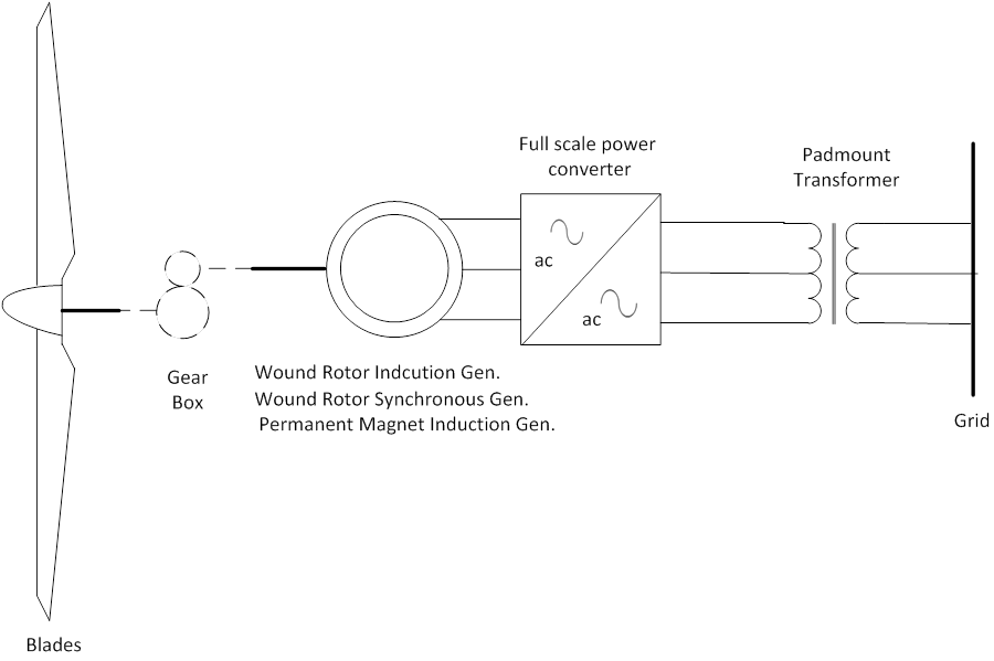
For Type 4 Wind Turbine Generators (WTGs), the generator is connected to a full power converter. In this configuration, a wide range of electrical generator topologies could be employed – Permanent Magnet Synchronous Generator, Wound Rotor Synchronous Generator, or Wound Rotor Induction Generator. Because all of the power from the turbine is processed by the static power converter, the specific characteristics and dynamics of the electrical generator are effectively isolated from the power grid. Full power conversion means that a back-to-back voltage-source converter is connected to the generator as illustrated in Figure on the right. The generator frequency and grid frequency are decoupled by using a voltage-source converter.
A modern static power converter utilizes power semiconductor devices (i.e. switches) that are capable of both controlled turn-on as well as turn-off. Further, the device characteristics enable switch transitions to occur very rapidly relative to a single cycle of 60 Hz voltage – nominal switching frequencies of a couple to several kHz are typical. This rapid switching speed, in combination with very powerful and inexpensive digital control, provides several advantages for distributed generation interface applications:
- Low waveform distortion with little passive filtering
- High-performance regulating capability
- High conversion efficiency
- Fast response to abnormal conditions, including disturbances, such as short-circuits on the power system
- Capability for reactive power control

Figure on the right depicts a simplified control schematic for a static power converter in grid-parallel operation. Since an individual wind turbine is likely small in rating relative to the short-circuit capability of the system to which it is connected, the voltage magnitude at this point will only be slightly influenced by the operation of the turbine. The control scheme, therefore, is designed to directly regulate the currents to be injected into this “stiff” voltage source. The ac line voltages, dc link voltage, and two of the three ac line currents – for a three-wire connection – are measured and provided to the main controller. The ac voltage and line currents are measured at a high resolution relative to 60 Hz, so that the controller is working with instantaneous values. By comparing the measured dc voltage to the desired value, the controller determines if the real power delivered to the ac system should be increased, decreased, or held at the present value. Such a simple regulation scheme works because there is no electric energy storage in the converter (except for that in the dc filter capacitor), so the energy flowing into the dc side of the converter must be matched at all times to that injected into the ac line. If these quantities do not match, the dc link voltage will either rise or fall, depending on the algebraic sign of the mismatch. The error in the dc voltage is fed into a PI (proportional-integral) regulator to generate a value representing the desired rms magnitude of the ac line currents. Another section of the control is processing the instantaneous value of the ac line voltage to serve as a reference or “template” for the currents to be produced by the converter. The desired instantaneous value of the line current is computed by multiplying the desired rms current magnitude by the present value from the template waveform. In the next stage of the control, often times called the “modulator” section, the desired instantaneous value of line current is compared to the measure value (in each phase). The modulator then determines the desired state of the six switches in the matrix based on the instantaneous current error in each phase of the line currents. The states are transmitted to the IGBT gate drivers, which then implement the state of each IGBT in the matrix as commanded by the controller. The process is then repeated at the next digital sampling interval of the overall control. The process is repeated thousands of times per single cycle of 60 Hz voltage. By using the line voltage as a template for the shape of the currents to be synthesized, synchronism is assured. Additionally, if there is no intentional phase shift introduced in the control calculations, the currents will be almost precisely – save for small delays introduced by the control itself – in phase with the line voltages, for unity power factor operation.
References
- ↑ Documentation, User Support, and Verification of Wind Turbine and Plant Models (DE-EE0001378), September 2012, [Online]. Available: http://www.osti.gov/bridge/servlets/purl/1051403/1051403.pdf. [Accessed May 2013].
