
Contents
Model Performance: Case 1 – Fault Event
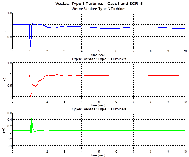
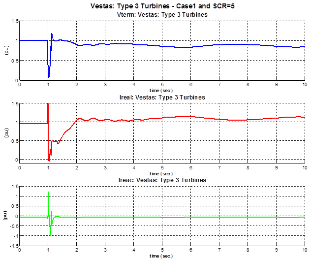
In this case a remote fault is applied to bus 12 for a duration of 6 cycles (0.1 sec).
Vestas: Type III – Case 1 and SCR=5
Vestas: Type III – Case 1 and SCR=10
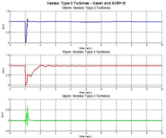
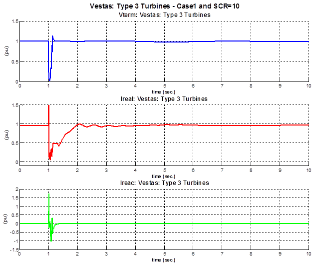
During low voltage events the turbine switches to current control mode, which gives the priority to the reactive current and injects reactive power to help the Low Voltage Ride Through (LVRT); Once the voltage is recovered above the threshold value of 0.85 pu, the turbine remains in the current control mode for additional 0.2 sec. After that, the turbine switches back to the power control mode. In this mode the reference power is being ramped up at the slope limit of 1 pu/sec.
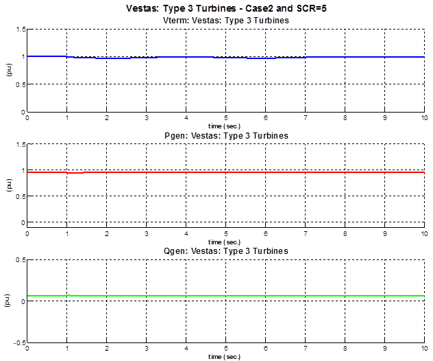
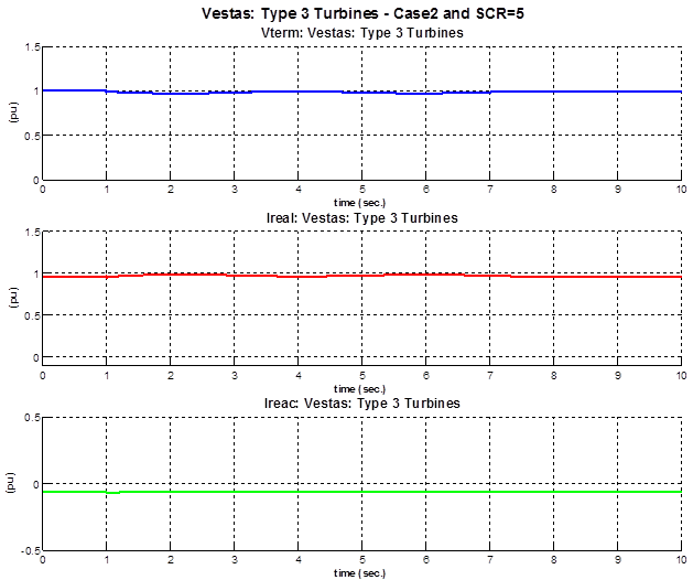
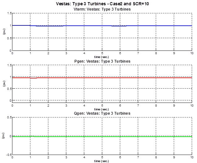
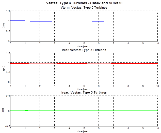
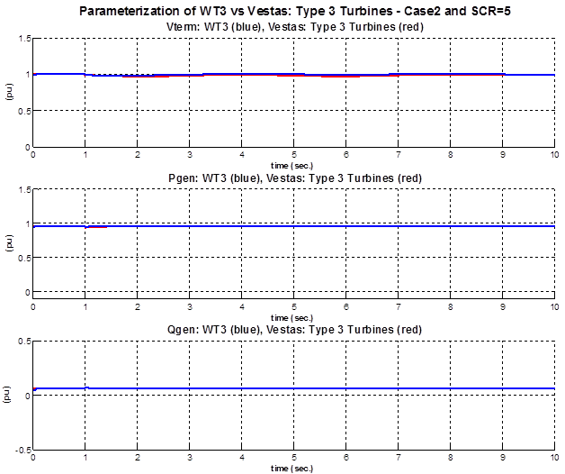
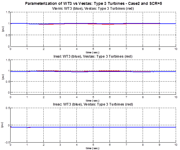
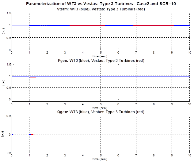
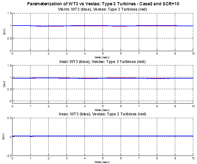
Model Performance: Case 2 – Under-Frequency Event
In this case a under frequency event is created by tripping the 100 MVA generation unit at bus 20.
Vestas: Type III – Case 2 and SCR=5
Vestas: Type III – Case 2 and SCR=10
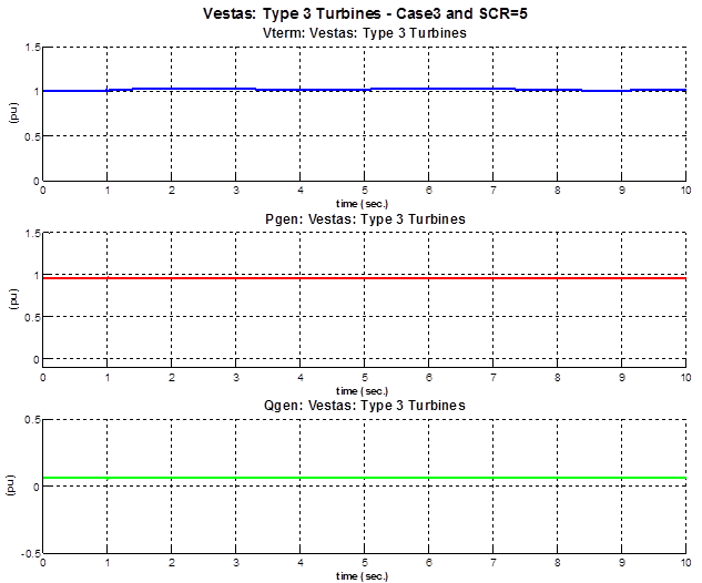
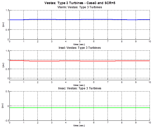
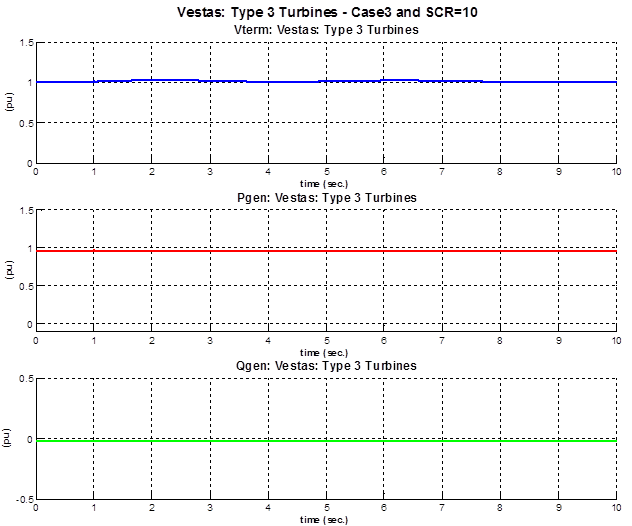
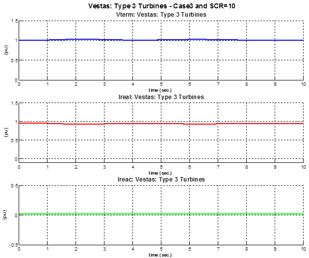
Model Performance: Case 3 – Over-Frequency Event
In this case a under frequency event is created by tripping the 100 MVA load at bus 11
Vestas: Type III – Case 3 and SCR=5
Vestas: Type III – Case 3 and SCR=10
Generic Model Parameterization – PSLF Environment
The parameter values shown in the table resulted from a compromise between the simulated cases (i.e. SCR 5 and SCR 10) and network conditions (i.e. fault, under- and over frequency).
|
There are four generic wind turbine models in PSLF for a type 3 wind turbine (WT3). These models are wt3g, wt3t, wt3e and wt3p. The wt3g model includes the generator and converters dynamics. The wt3t model includes the wind aerodynamic model and the single or double mass shaft compliance model. The wt3p includes the pitch controller model. Finally, the wt3e model contains the real and reactive control models. The values for the parameters resulted from a compromise between the two cases (SCR 5 and SCR 10). The set of parameters had to be tuned to satisfactory match the results of dynamic simulation for the VSM and the generic WT3 model for both SCR cases. | |||||||||||||||||||||||||||||||||||||||||||||||||||||||||||||||||||||||||||||||||||||||||||||||||||||||||||||||||||||||||||||||||
Parameterization: Case 1 – Fault Event
Parameterization of WT3 vs Vestas: Type III – Case 1 and SCR=5
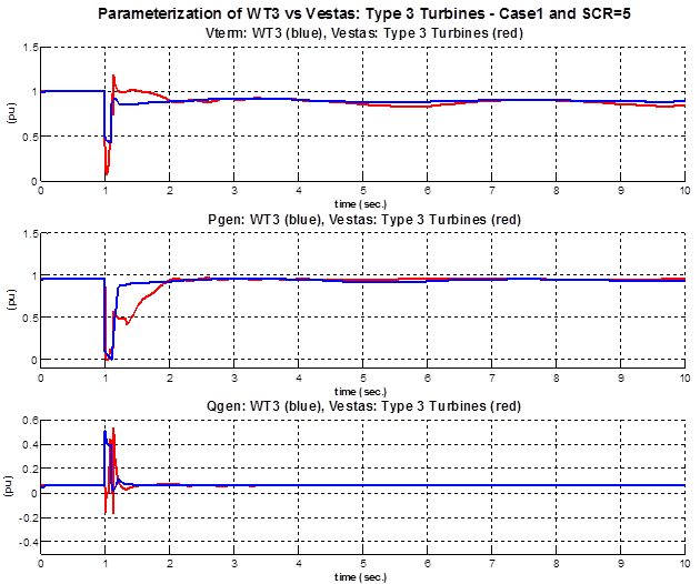
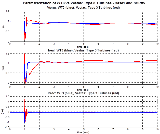
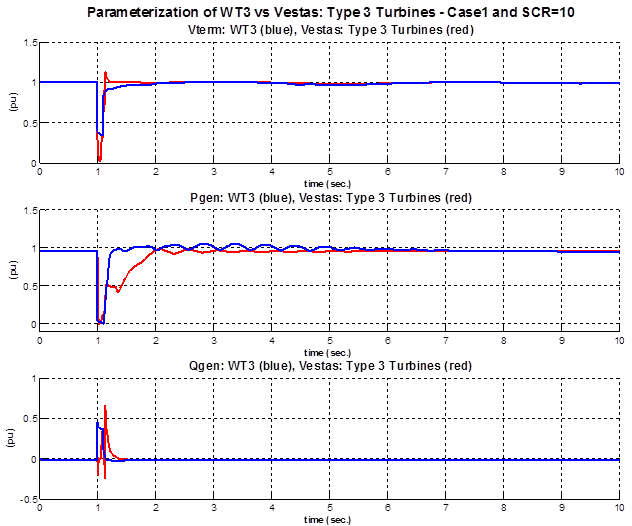
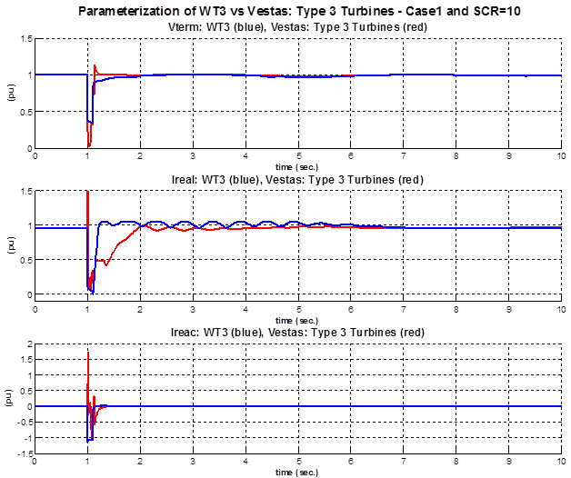
Parameterization of WT3 vs Vestas: Type III – Case 1 and SCR=10
Parameterization: Case 2 – Under-Frequency Event
Parameterization of WT3 vs Vestas: Type III – Case 2 and SCR=5
Parameterization of WT3 vs Vestas: Type III – Case 2 and SCR=10
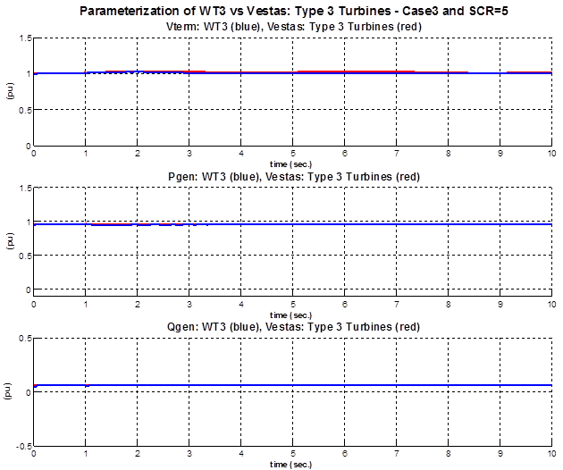
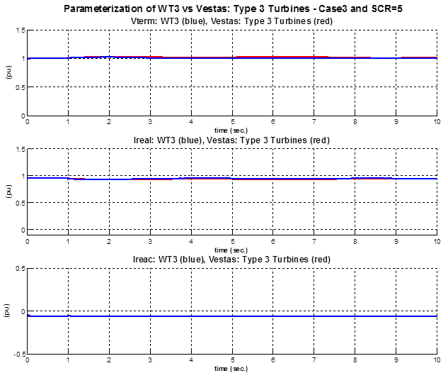
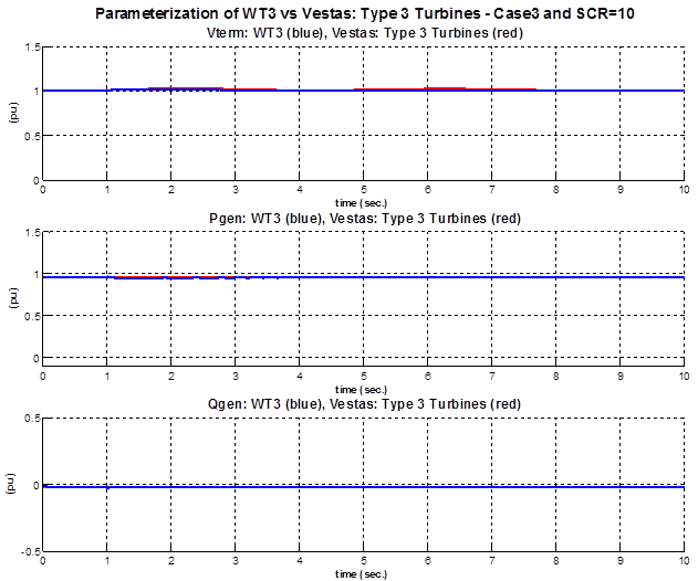
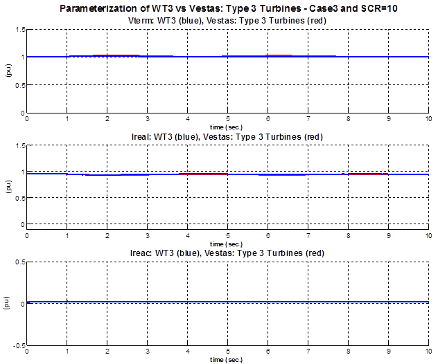
Parameterization: Case 3 – Over-Frequency Event
Parameterization of WT3 vs Vestas: Type III – Case 3 and SCR=5
Parameterization of WT3 vs Vestas: Type III – Case 3 and SCR=10
Results Validation
For cases 2 and 3 (over frequency and under frequency events), the response of the generic model matches the response of the VSM in the frequency range of interest. However, for case 1 (fault event), the response of the generic model matches the response of the VSM poorly. In other words, while the generic models are a good representation of the Vestas: Type 3 turbine VSM behavior during frequency events, they are rather a poor alternative for severe fault events.
Vendor Specific Model Validation
The dynamic Low Voltage Right Through (LVRT) performance during different residual voltage levels and dip durations is documented in this section. Specifically, detailed PSCAD model behavior is compared against the vendor specific PSSE implementation of type 3 turbines.
LVRT Performance During a 0.3 pu Residual Voltage and a Dip Duration of 2 seconds
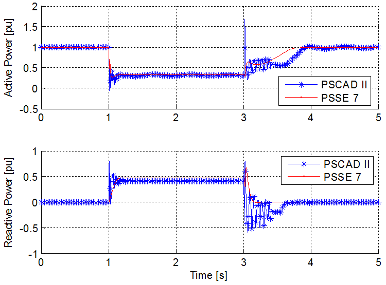
Active power and reactive power validation
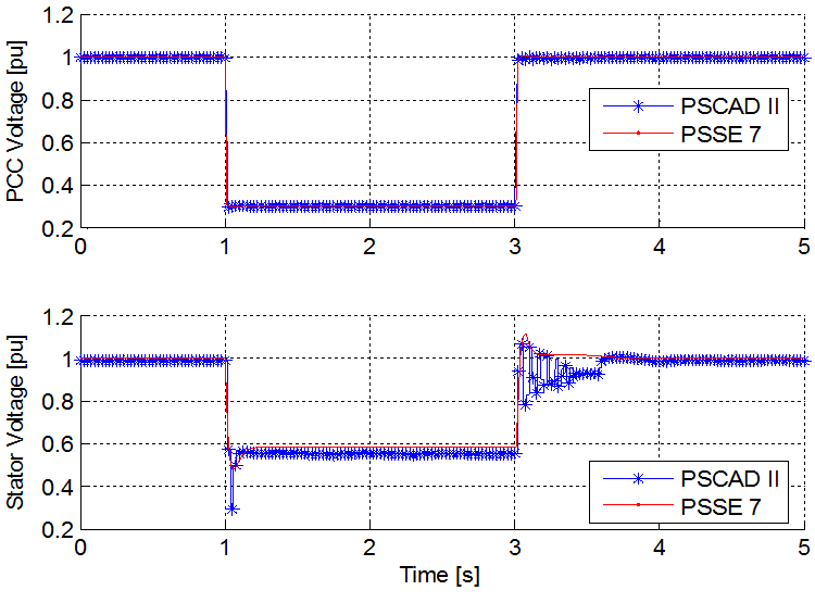
Stator voltage and PCC voltage validation
LVRT Performance During a 0.3 pu Residual Voltage and a Dip Duration of 0.6 seconds
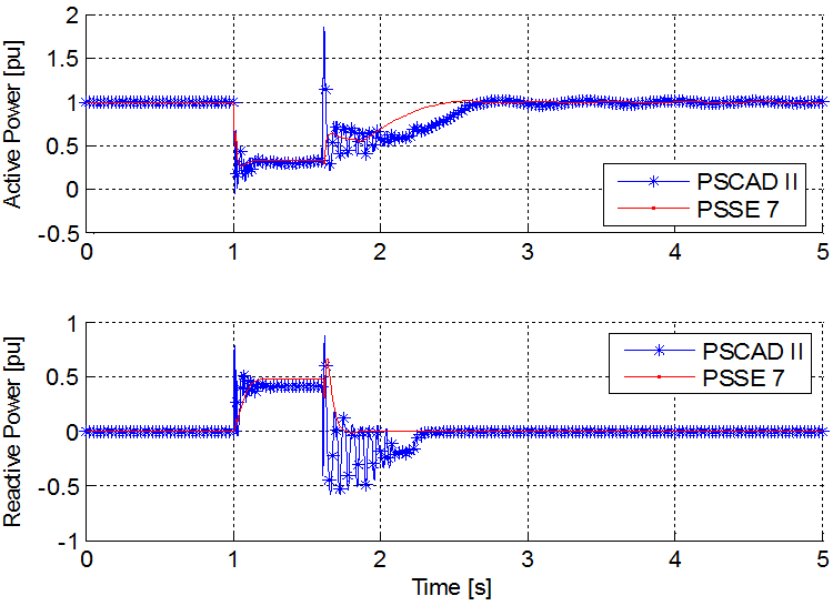
Active power and reactive power validation
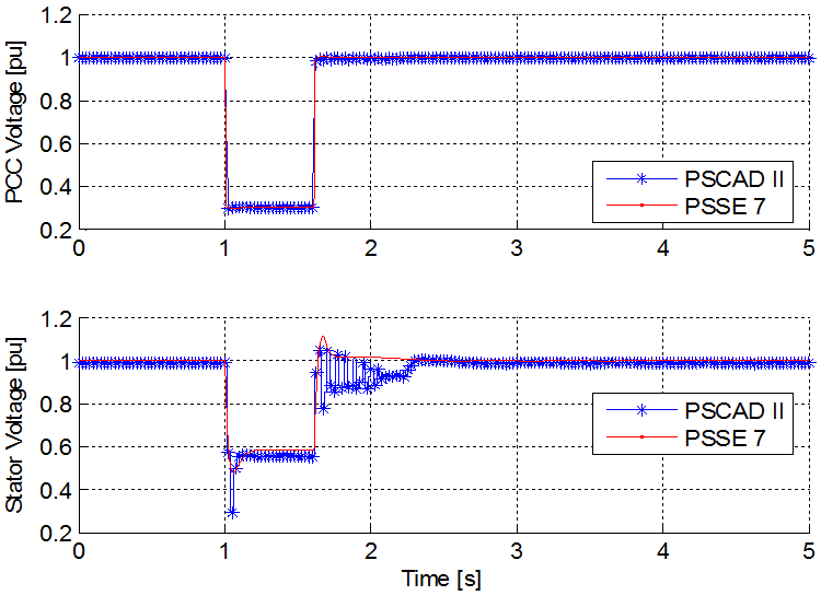
Stator voltage and PCC voltage validation
LVRT Performance During a 0 pu Residual Voltage and a Dip Duration of 0.3 seconds
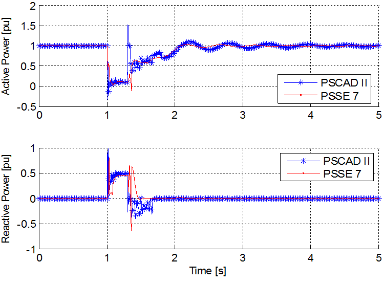
Active power and reactive power validation
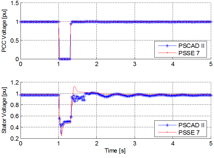
Stator voltage and PCC voltage validation