
Author: WECC REMTF[1]
Dynamic representation of large-scale PV plants requires the use of three renewable energy (RE) modules:
- REGC_A – Generator/Converter (inverter) interface with the grid.
- REEC_B – module, used to represent the Electrical Controls of the inverters. It acts on the active and reactive power reference from the REPC_A module, with feedback of terminal voltage and generator power output, and provides real and reactive current commands to the REGC_A module.
- REPC_A – Plant Controller.
These modules, in addition to others, are also used to represent wind and PV power plants.
Dynamic representation of distribution-connected small PV plants or multiple PV plants requires the use of one renewable energy (RE) modules:
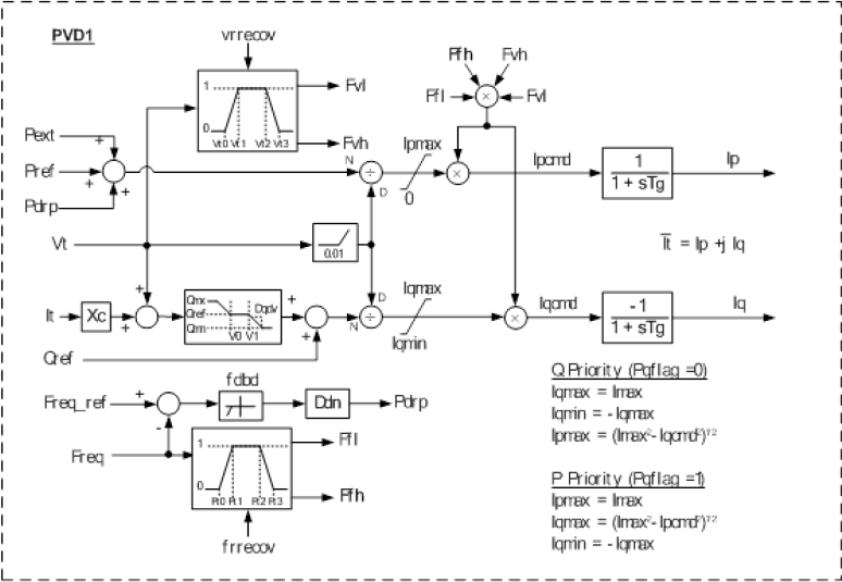
- PVD1 – module, is recommended to represent distribution-connected small PV plants or multiple PV plants aggregated at a high voltage bus that is represented in power flow.
Key Modeling Assumptions
Unlike central station PV plants, distributed PV systems are connected at the distribution level, and thus are under state jurisdiction. Reliability and interconnection requirements, while varying from state to state, tend to reflect the requirements outlined in IEEE Standard 1547. In contrast with NERC and WECC central station reliability requirements, distributed PV systems at this time normally do not participate in steady state voltage regulation, and tighter bounds on operation for off-nominal voltage and frequency conditions result in significantly different fault ride-through capability.
In the near term, it is anticipated that the PV inverters applied in distributed systems will continue to comply with IEEE 1547, and will operate under constant power factor or constant reactive power modes of operation. The elimination of the closed-loop voltage regulator dynamics, along with the elimination of the DC dynamics, allows for substantial simplification of the model with respect to that of the large-scale PV plants. However, unlike a large-scale PV plant, the terminal voltages seen by the individual inverters within the composite load in the bulk system dynamic model are likely to vary substantially. A different protection model is used to capture the effect of the diverse terminal conditions on the aggregate generation.
| PVD1 Input Parameters | ||
|---|---|---|
| Name | Description | Typical Values |
| igreg | Remote bus number for droop response (0 = generator terminal bus) | 0 |
| qmx | Maximum reactive power command (pu on mbase) | 0.33 |
| qmn | Minimum reactive power command (pu on mbase) | -0.33 |
| v0 | Lower limit of deadband for voltage droop response (pu) | – |
| v1 | Upper limit of deadband for voltage droop response (pu) | – |
| dqdv | Voltage droop response characteristic | – |
| ialim | Apparent current limit (pu on mbase) | 1.0 to 1.3 |
| vt0 | Voltage tripping response curve point 0 (pu) | 0.88 |
| vt1 | Voltage tripping response curve point 1 (pu) | 0.90 |
| vt2 | Voltage tripping response curve point 2 (pu) | 1.1 |
| vt3 | Voltage tripping response curve point 3 (pu) | 1.2 |
| vrflag | Voltage tripping is latching (0) or partially self-resetting (>0 and ≤1) | 0 |
| ft0 | Frequency tripping response curve point 0 (pu) | 59.5 |
| ft1 | Frequency tripping response curve point 1 (pu) | 59.7 |
| ft2 | Frequency tripping response curve point 2 (pu) | 60.3 |
| ft3 | Frequency tripping response curve point 3 (pu) | 60.5 |
| frflag | Frequency trip ping is latching (0) or partially self-resetting (>0 and ≤1) | 0 |
| tip | Inverter active current lag time constant (s) | 0.02 |
| tiq | Inverter reactive current lag time constant (s) | 0.02 |
| PVD1 Internal Variables | ||
| Name | Description | |
| vterm | Terminal voltage (pu, from network solution) | |
| pref | Initial active power (pu on mbase, from power flow) | |
| fterm | Terminal frequency deviation (pu, from network solution) | |
| qref | Initial reactive power (pu on mbase, from power flow) | |
| ipmax | Dynamic active current limit (pu on mbase) | |
| iqmax | Dynamic reactive current limit (pu on mbase) | |
| iqmin | Dynamic reactive current limit (pu on mbase, = -iqmax) | |
| iqcmd | Desired reactive current (pu on mbase) | |
| ipcmd | Desired active current (pu on mbase) | |
References
- ↑ WECC REMTF, WECC PV Power Plant Dynamic Modeling Guide, April 2014, [Online]. Available: https://www.wecc.biz/Reliability/WECC%20Solar%20Plant%20Dynamic%20Modeling%20Guidelines.pdf. [Accessed June 2015].