Models that capture the aggregated behavior of all components in a wind plant as seen from the interconnection point to the transmission network are the most useful and sometimes practically required for large power system studies. This section discusses how these components contributed to behavior of the wind plant as a single entity connected to the transmission network for steady-state and dynamic conditions.
Contents
Steady-State and Small-Signal Behavior
For power flow calculations, a wind plant can obviously be represented as a single generating unit at the interconnection substation. Determining the equivalent “reactive capability” of the plant, however, can be complicated since it will be a function of a large number of elements within the plant – turbine reactive compensation, reactive losses in collector lines, auxiliary compensation equipment such as collector line capacitor banks, etc. While fairly standard and well-known for conventional generating units, this characteristic has not been considered explicitly for many of the plants developed over the past decade. Net reactive power is also a function of voltage if shunt capacitors are present as part of the plant reactive compensation scheme. The dynamic nature of the wind resource can introduce a new dimension to power system studies, especially where the transmission interconnection is weak. Reactive power support for maintaining target voltages at the transmission interconnection will vary with the real power injected. Temporal variation of wind plant aggregate power is a very complicated function of a number of plant parameters and variables, but it also can be a defining factor for the dynamic characteristics of the reactive compensation system. Additionally, the reactive compensation devices within the plant – turbines (shunt capacitors or advanced control), collector line capacitor bank, and possibly interconnect substation-based equipment – are dynamic devices themselves, with set points and delay for toggling on or off of switched devices and continuous control for static var capabilities. Some of the factors that influence the variability of the aggregate production of a wind plant include
- Variations in wind speed at each turbine location in the plant;
- Topographical features that introduce turbulence and shear into the moving air stream across the geographical expanse of the wind plant;
- The mechanical inertia of individual turbines, which influences how the wind speed variations, turbulence, and wind shear affect the output of individual turbines
- The wind turbine control scheme, including the generator control and pitch regulation systems that determine how the electric power at the terminals of the turbine is influenced by fluctuating prime mover input;
- The number of turbines within the plant, since a larger number of turbines implies a larger geographical area for plant, and more statistical diversity in the local characteristics that contribute to output fluctuations;
- The grouping of turbines within the plant – if turbines are grouped into “strings”, rather than more uniformly distributed over the area of the plant, local fluctuations in wind speed will affect more than a single turbine at an instant of time.
Wind generation is often characterized as “intermittent”, but, to better understand how it can impact power system operations, it is useful to consider the output variability in more detail. On the shortest time scales, say tens of seconds to minutes, the output of a wind plant can fluctuate because of varying wind speeds at the individual turbines comprising the plant due to effects of terrain and turbulence in the moving air stream. This is more likely the case in light to moderate winds, as modern wind turbines are capable of holding the output power “flat” for wind speed at or above the rated value. Measurement data shows that the fluctuations on this time scale as a fraction of the plant rating decrease in magnitude as the number of turbines in the plant increases. Over longer time periods – tens of minutes to hours – wind plant generation will again exhibit fluctuation, and may also trend down or up as the larger scale meteorology responsible for the wind changes. Passage of a weather front is an example. Experience is showing that these trends can be predicted, but the accuracy of the prediction degrades quickly with time. Forecasts for the next hour, for instance will be much better than those for several hours ahead. Longer-term forecasting for the next day or week is even less accurate, especially when timing is important. Predictions of a weather front passing an area tomorrow can be relatively accurate, but the accuracy for predicting which hour it will pass will be much lower. “Intermittent”, as the term is applied to wind generation, encompasses both the fluctuating characteristics along with the degree of uncertainty about when the resource will actually produce. Both of these attributes are important for power system engineers and operators who have come to understand well the fluctuations and uncertainties inherent in conventional generating resources and system loads. Because wind generation is new, these characteristics are only beginning to be quantified, and procedures for rigorously considering them in system studies have yet to be developed. As of this writing, there are no practical analytical methods for characterizing the output fluctuations from a large wind plant. Direct measurements from operating wind plants, however, are providing some important insights into the complicated interaction of the factors listed above. The National Renewable Energy Laboratory (NREL) launched a program in CY2000 to collect high-resolution electrical measurement data from operating wind plants across the U.S. The database being compiled by NREL consists of continuous one-second samples of voltage, current, real power, and reactive power from wind plants in the Pacific Northwest, the upper Great Plains, and West Texas. Preliminary analysis of this data has revealed much about the behavior of bulk-scale wind plants consisting of large numbers of individual turbines spread out over a significant geographical area. As the number of individual turbines increases, the per-unit variations in the aggregate output decline substantially. This characteristic is a critical factor for grid studies, as it provides a basis for bounding the changes in real and reactive power over time that can influence system voltage and related indices such as flicker, as well as the impact on the generation/load balance in the control area.
Dynamic Response

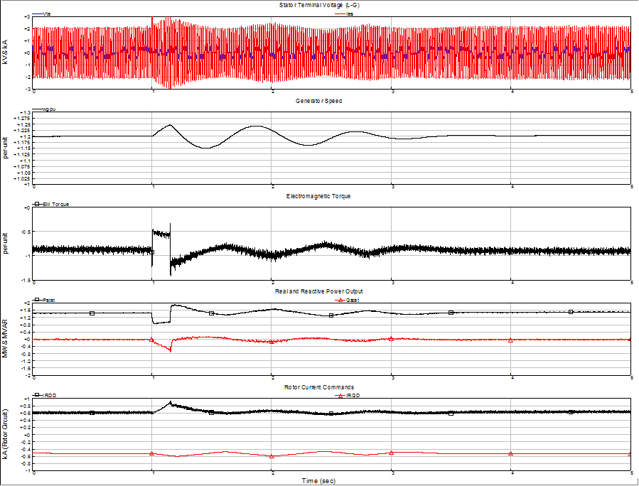
The electrical and mechanical technologies which comprise commercial wind turbines differ dramatically from the familiar synchronous generator and auxiliary systems that are used to represent almost all conventional generating equipment. And, instead of a small number of very large generating units, bulk wind plants can be made up of a very large number of relatively small machines. Until quite recently, these attributes have presented a difficult challenge to power system engineers engaged in evaluating transmission system impacts of large wind generation facilities. Evaluating the dynamic response of the electric power system during and immediately following major disturbances such as faults is a critical engineering function for ensuring system security and reliability. Now that wind plants make up a non-negligible fraction of the generation assets in some control areas, their contribution to the system dynamic performance must be considered. When subjected to a sudden and substantial change in terminal voltage or frequency, both the mechanical and electrical elements of the turbine along with the associated control systems influence its behavior. Consider the doubly-fed induction generator with flux vector control of torque via the power converter on the rotor circuit. When a fault on the transmission network causes the voltage at its terminals to sag to some fraction of normal,
- The magnitude of the main flux in the machine begins to decay in response to the reduced terminal voltage, and the position of the flux vector may suddenly change if there is a phase shift associated with the fault voltage.
- The rotor power converter control almost instantaneously adjusts the quadrature axis rotor currents to “line up” with the new rotor flux vector.
- Since the rotor flux is no longer at the pre-fault value, the stator power of the machine is reduced accordingly. In response, the power converter control may try to increase the torque-producing component of rotor current.
- Because the electrical power output of the machine is now lower than the pre-fault value, there is net accelerating torque on the mechanical system which will increase the rotational speed of the machine.
- The increased rotational speed will cause the turbine blades to begin pitching to reduce the mechanical torque input to the machine and reduce speed.
- When the fault is cleared and the terminal voltage returns to near normal, the rotor power converter control will readjust the position of the rotor current vector to again line up with the rotor flux vector.
- Electric power output will jump back to (or slightly above, if the rotor current had been increased by the controller during the fault) the pre-fault value. Since mechanical power had been reduced by the pitch system, net decelerating torque on the mechanical system will cause rotational speed to decrease.
.png)
-
- The sudden changes in electromagnetic torque applied by the generator to the rotating shaft (at fault inception and clearing) excite the main mechanical resonance between the turbine blades and the generator inertia, such that these masses are now oscillating out of phase around the average speed of the rotating system.
- The oscillations in generator speed may be fed through the control system to produce oscillations in electric power at the stator terminals of the machine.
The response is depicted graphically in Figure on the right, and Figure on the left shows an expanded view around the initiation and clearing of the system fault. Note how the vector control algorithm maintains control of the rotor (and stator) currents except for a few milliseconds at the beginning and end of the fault.
While there are some similarities to the response of a synchronous generator to the same disturbance, the markedly different equipment and control comprising the wind turbine lead to a difference dynamic response. While the sequence above is only an example for one type of wind turbine, it is indicative of the behavior that needs to be represented in dynamic simulations of the entire power system. In addition, the response described is for a single turbine. What is important from the perspective of the power system is the aggregate response of all the turbines in the wind plant, along with the influence of any other dynamic elements such as static compensation or switched elements. Research is only beginning into electro-dynamic equivalents for wind plants. There is agreement on a few general guidelines and principles for developing these dynamic equivalents. For remote disturbances – those originating on the transmission network, not within the wind plant itself – individual turbines can be considered coherent, i.e. they response as if they were a large single machine of equivalent aggregate rating. This assumption is based on all turbines being of identical type and parameters, and that they “see” the disturbance at precisely the same instant and in roughly the same degree. With some turbine technologies, there are nonlinearities in certain of the control blocks such that the response may be dependent on the pre-fault conditions at the turbine, namely the assumed generation level as a fraction of the rated value. If maximum generation conditions are being studied, then all turbines at the same pre-fault generation level is a good one. If for some reason partial generation conditions are of interest, aggregate dynamic performance of the plant could depend on how the total generation is allocated to individual turbines. Because of the extensive medium voltage collector system that is part of many large wind plants, there is potentially an issue with differing pre-fault terminal voltages at turbines dependent on generation level and electrical location within the plant. And, as with the steady-state and small signal characterizations, the response of the plant in terms of reactive power may also be difficult to capture, unless the behavior at the interconnection bus bar is dominated by a single device such as a static var compensator located at the substation. Fortunately, most of these detailed questions are likely of secondary importance, especially where the focus is on the power system as a whole and not some particular aspect of the wind plant response. Until new research findings indicate otherwise, relatively simple dynamic equivalents consisting of a single or small number of equivalent machines at the interconnection substations is the recommended approach.
Transient Response
Dynamic simulations and studies of the interconnected power system are based on a number of assumptions to facilitate some simplifications in the representation of the dynamic components of the system. For some investigations, such simplifications are not valid or can obscure the aspects of the system model critical for the study. Studies of sub-synchronous torsional interaction, control interactions, inadvertent islanding, etc. may require models with more detail than those used for system dynamic studies. Full transient models of all but the simple wind turbine technologies require information and engineering detail that can only be obtained from the wind turbine manufacturer. Studies of these types should be conducted collaboratively with technical personnel from the turbine designer.
Short Circuit Contributions
Little guidance exists for calculating short-circuit contributions from large wind generation facilities. Analytical approaches are complicated for the following reasons:
- Commercial wind turbines employ induction machines for electromechanical energy conversion, which do not strictly conform to the standard procedures and assumptions used in calculation of short-circuit contributions on the transmission network.
- Generator control technologies employed in wind turbines– e.g. scalar or vector control of rotor current in a wound-rotor induction machine – can substantially modify the behavior of the induction machine in response to a sudden drop in terminal voltage, further complicating calculation of terminal currents during such conditions
- Wind plants are composed of large numbers of relatively small generators, interconnected by an extensive medium-voltage network that itself influence fault contributions
The short-circuit behavior of a squirrel-cage induction generator is fairly well known, and procedures are spelled out in the technical literature (such as the IEEE Brown Book) for considering these machines in short-circuit studies. These recommendations, however, apply most directly to fault studies within large industrial facilities, and may require adaptation for transmission system fault studies. In the remaining cases of the wound-rotor induction machines, the external components and accompanying control have very significant influence on the machine under network fault conditions, assuming that the control systems themselves are not bypassed or rendered inoperative as a consequence of reduced terminal voltage at the turbine. The following paragraphs are intended as a qualitative description of the characteristics of the various wind turbine generator technologies under network fault conditions.
Direct-Connect Squirrel Cage Induction Generator

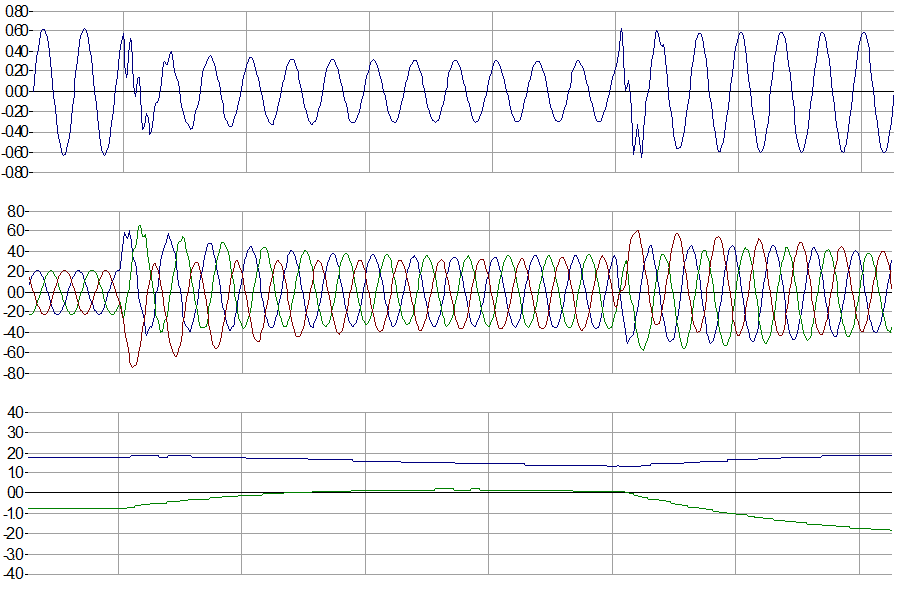
Induction generators are essentially induction motors that are driven at speed above their nameplate synchronous speed by some prime mover. Magnetic excitation necessary for torque production and power flow is drawn from the power supply system. The electric current necessary for magnetizing the iron core is responsible for much of the reactive power required by an induction machine. When the source of excitation is removed from an induction machine, the main flux field collapses and torque production or power flow is no longer possible. It does take a finite amount of time for this field to collapse, however, during which time an induction machine will contribute current to a short-circuit on the power system. Also, if voltage is just reduced rather than removed completely as the result of a downstream fault, the main flux will decay to some new value, but provide necessary excitation for the machine to contribute to the fault. Contributions from induction motors are rarely considered in utility fault studies, but can be an important consideration for protective device coordination and rating within some industrial facilities. The IEEE Brown Book (Standard 399-1997) “IEEE Recommended Practice for Industrial and Commercial Power Systems Analysis” details procedures for calculating induction motor and generator contributions to short-circuits within facilities. Figure on the right illustrates the behavior of a wind turbine employing a line-connected induction generator during a fault on the supply network. In the first cycle following fault inception, stator currents quickly build up to a value several times the rated current of the machine. The contribution during the first cycle can be estimated as the sum of: 1) a sinsusoidal component approximately equal to the pre-fault terminal voltage divided by the sum of the subtransient reactance of the generator and the reactance of the equivalent network to the point of fault, and 2) a uni-directional (dc) component that depends on the reactance to resistance (X/R) ratio of the equivalent system impedance and the precise point on the terminal voltage wave where the fault is initiated. Both components decay in magnitude as the fault persists. The dc component decays at a rate governed by the X/R ratio. The decrease in the magnitude of the sinusoidal component is due to the decay in the main flux of the machine. After a few cycles, the dc component has vanished, and the sinusoidal component has decreased in magnitude. It should be noted here that precise calculation of the short-circuit contribution requires a time-domain computer simulation with a relatively detailed differential equation representation of the induction machine. The aforementioned IEEE Brown Book acknowledges as much, and prescribes an approximate method for defining two equivalent reactances for the induction machine – one to be used for calculating the first cycle contribution, the other for a later time during the fault that would be associated with breaker clearing or interrupting requirements.
Doubly-Fed Induction Generator with Vector Control of Rotor Currents


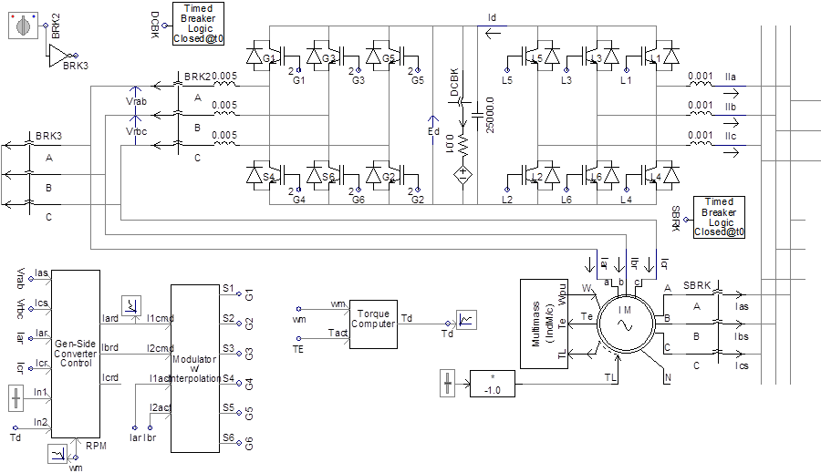
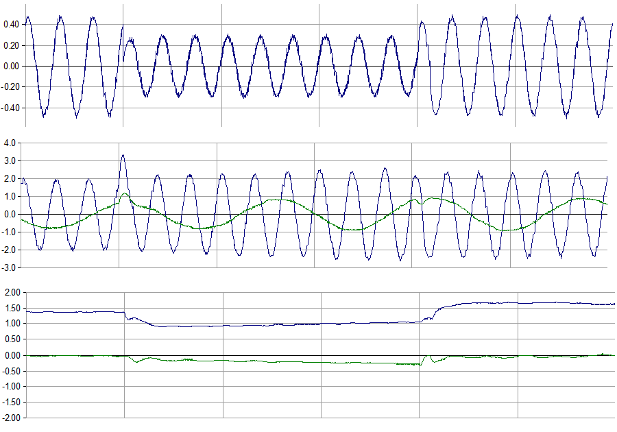
The 1.5 MW wind turbine from GE and its predecessor, the 750 kW turbines from Enron, are also based on a wound rotor induction generator. In these turbines, however, the rotor circuit is powered by a bi-directional static power converter. The fast response of the power converter coupled with sophistical algorithms in the turbine and converter controller sections allows for precise and continuous adjustment of the instantaneous currents in the rotor circuits of the induction machine. Nearly instantaneous control of electromagnetic torque and turbine power factor is possible with this scheme. The fast action of the turbine and converter controls can limit the stator currents during a fault on the grid. Figure on the left details the turbine operation during a 150 ms grid fault. When the fault is initiated, the sudden change in terminal voltage magnitude and phase angle causes the power converter to momentarily “lose control” of the rotor currents, which is manifested as a one-quarter cycle “surge” in the stator current. Control is regained quickly, and the stator currents settle down to near their pre-fault value for the duration of the fault event (The slight rise in stator current magnitude during the fault is due to control actions attempting to restore the electromagnetic torque to the pre-fault value). When the fault is cleared, the phase and magnitude of terminal voltage again change suddenly, inducing another short-duration transient in the stator current. Again, however, control is regained, and stator currents return to the level desired by the turbine control.
It should be noted, however, that if the rotor power converter is bypassed, such as might be done to protect it from high rotor circuit voltage, the behavior of the turbine during the fault would be better characterized as a conventional induction machine. GE Power System Energy Consulting has developed an internal white paper specifying how the GE Wind Turbine would perform under conditions of rotor converter bypass.
