
Author: EnerNex[1]
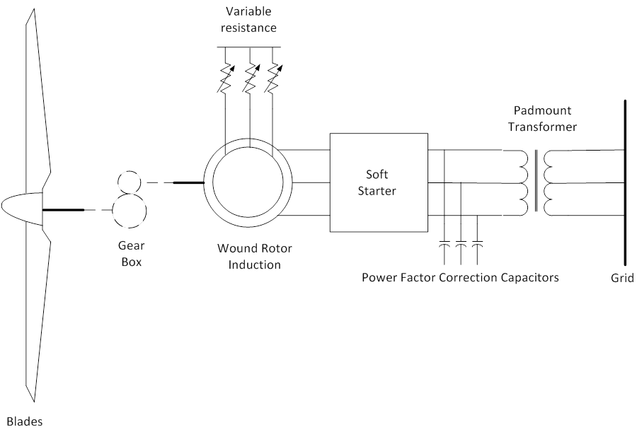
In a squirrel-cage induction generator, the rotor “circuits” are fictitious and not accessible external to the machine, and the induced currents responsible for torque generation are strictly a function of the slip speed. The turbine shown in Figure on the right utilizes a wound-rotor induction machine, where each of the three discrete rotor winding assemblies is electrically accessible via slip rings on the machine shaft. This provides for modification of the rotor circuit quantities and manipulation of the rotor currents, and therefore the electromagnetic torque production. The Type II turbines utilize a system for controlling the magnitude of the rotor currents in the induction generator over the operating speed range of the turbine. The current controller system usually consists of an external resistor network and a power electronics module that modulates the voltage across the resistors to maintain a commanded rotor current magnitude. The operation of the controller is quite fast, such that it is capable of holding the turbine output power constant for even gusting winds above rated wind speed, and significantly influences the dynamic response of the turbine to disturbances on the grid.
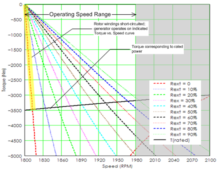
The operation of the scalar rotor current control under steady conditions is illustrated in Figure on the left. The continuously variable rotor resistance effectively allows the generator to operate on an infinite number of torque vs. speed curves. In the figure, curves are shown for 10% increments of the total external rotor resistance. The maximum torque line shown on the graph corresponds to constant power at the nominal value. The curve is sloped as torque must decrease as speed increases to maintain constant power.
References
- ↑ Documentation, User Support, and Verification of Wind Turbine and Plant Models (DE-EE0001378), September 2012, [Online]. Available: http://www.osti.gov/bridge/servlets/purl/1051403/1051403.pdf. [Accessed May 2013].