
The WT2 WECC wind turbine stability model was developed to simulate performance of a wind turbine employing a wound rotor induction generator with the variable rotor resistance control (Type II). WT2 is currently implemented in Siemens PTI – Power System Simulation for Engineering (PSSE [1]), GE – Positive Sequence Load Flow (PSLF [2]), and other simulation programs used in WECC.
The model consists of four components: generator, wind turbine, pseudo governor, and rotor resistance controller. The generator is an induction generator with provisions for adjusting its rotor resistance via the rotor resistance controller. This controller has as inputs the rotor speed and generator electrical power; the model calculates the portion of the available rotor resistance to be added to the rotor resistance included in the generator module.[3]
Contents
PSSE

The WT2 modeling package includes 4 main models as follows:
- Generator/converter model WT2G
- Rotor resistance control model for the WT2 Generic Wind Model WT2E
- Two mass turbine model for the WT2 Generic Wind Model WT21T
- Pseudo-governor model for the WT2 Generic Wind Model WT12A
Control input parameters:
- Most of the parameters are given and unique for a specific turbine.
- Available in PSSE [1] and PSLF [2]
- The compensating capacitor is not dynamically modeled but it should be provided and initialized from load flow data.
- WIND PLANT SPECIFIC ADJUSTMENT:
- Plant Size
- Dual mass versus single mass
Induction Generator Model (WT2G)
The generator model WT2G is based on the standard PSSE [1] model of the induction generator CIMTR3. This model takes into account the rotor flux dynamics and can be used for single cage or double cage machines. At initialization this model calculates the reactive power consumption of the machine Qact at given terminal voltage and MW-dispatch. It places a “hidden” shunt on the machine terminal bus, with the size equal to a difference between Qgen from the power flow and Qact. It also determines what portion of available external rotor resistance should be added to fit the steady-state operating point.
| Input data for WT2G | ||
|---|---|---|
| CONs | Default Value | Description |
| J | 0.12602 | XA, stator reactance, pu |
| J+1 | 6.8399 | XM, magnetizing reactance, pu |
| J+2 | 0.18084 | X1, rotor reactance, pu |
| J+3 | 0.4419e-02 | R_ROT_MACH, rotor resistance, pu |
| J+4 | 0.10994 | R_ROT_MAX, a sum of R_ROT_MACH and total external resistance, pu |
| J+5 | 1.00 | E1, first saturation coordinate |
| J+6 | 0.0 | SE1, first saturation factor |
| J+7 | 1.20 | E2, second saturation coordinate |
| J+8 | 0.0 | SE2, second saturation factor |
| J+9 | 0.0 | POWER_REF_1, first of 5 coordinate pairs of the power-slip curve |
| J+10 | 0.217e-01 | POWER_REF_2 |
| J+11 | 0.8988 | POWER_REF_3 |
| J+12 | 0.90 | POWER_REF_4 |
| J+13 | 0.905 | POWER_REF_5 |
| J+14 | 0.0 | SLIP_1 |
| J+15 | 0.54e-01 | SLIP_2 |
| J+16 | 0.20e-01 | SLIP_3 |
| J+17 | 0.40e-01 | SLIP_4 |
| J+18 | 0.10 | SLIP_5 |
| STATEs | Description | |
| K | Eq’, transient flux q-component | |
| K+1 | Ed’, transient flux d-component | |
| K+2 | Internal | |
| VARs | Description | |
| L | Admittance of the hidden shunt | |
| L+1 | Machine Q | |
| L+2 | Telec | |
Turbine Model (WT12T)
The turbine WT12T model uses the two-mass representation of the wind turbine shaft drive train. It calculates the speed deviations of the rotor on the machine and on the blade sides. By setting the turbine inertia fraction Htfrac = 0 the model can be switched to a conventional single mass representation.
| Input data for WT12T | ||
|---|---|---|
| CONs | Default Value | Description |
| J | 3.46 | H, Total inertia constant, sec |
| J+1 | 0.0 | DAMP, Machine damping factor, pu P/pu speed |
| J+2 | 0.81 | Htfrac, Turbine inertia fraction (Hturb/H) |
| J+3 | 1.50 | Freq1, First shaft torsional resonant frequency, Hz |
| J+4 | 0.30 | Dshaft, Shaft damping factor (pu) |
| STATEs | Description | |
| K | Shaft twist angle, rad. | |
| K+1 | Turbine rotor speed deviation, pu | |
| K+2 | Generator speed deviation, pu | |
| K+3 | Generator rotor angle deviation, pu | |
| VARs | Description | |
| L | Paero on the rotor blade side, pu | |
| L+1 | Initial rotor slip | |
| L+2 | Initial internal angle | |
- Block Diagram (Dual Mass)
.png)
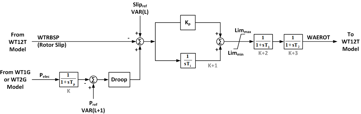
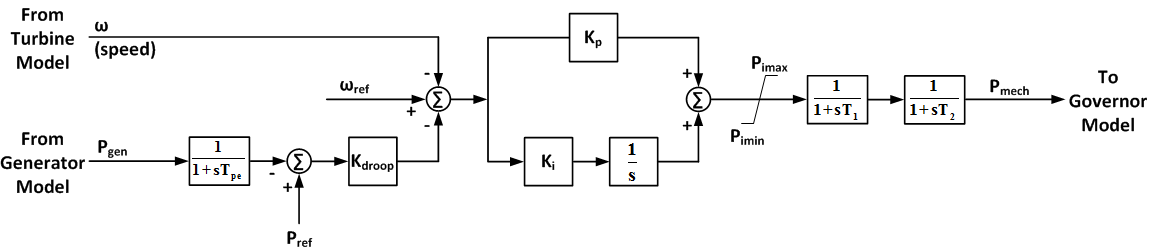
Pseudo Governor Model (WT12A)
The pseudo governor model WT12A is an attempt to simplify and generalize calculation of the aero-torque. This model was designed and developed after thorough investigation of aero-dynamic characteristics and pitch control of several vendor specific wind turbines. Finally the arrangement shown below was suggested. The model uses two inputs, one in terms of the blade rotor speed deviation and another in terms of the real power at the machine terminals. These two inputs combined together are processed by a PI controller with non-wind-up limits. The filtered output is the mechanical power on the rotor blade side which is used by the WT12T model.
| Input data for WT12A | ||
|---|---|---|
| CONs | Default Value | Description |
| J | 0.1500e-01 | Droop |
| J+1 | 20.0 | Kp, proportional gain, pu |
| J+2 | 1.00 | Ti, integrator time constant, sec. |
| J+3 | 0.10 | T1, output filter 1 time constant, sec. |
| J+4 | 0.10 | T2, output filter 2 time constant, sec. |
| J+5 | 0.10 | Tp, power filter time constant, sec. |
| J+6 | 1.00 | Limmax, maximum output limit |
| J+7 | 0.25 | Limmin, minimum output limit |
| STATEs | Description | |
| K | Power filter | |
| K+1 | PI integrator | |
| K+2 | Output filter 1 | |
| K+3 | Output filter 2 | |
| VARs | Description | |
| L | Reference | |
| L+1 | Power reference | |
- Block Diagram
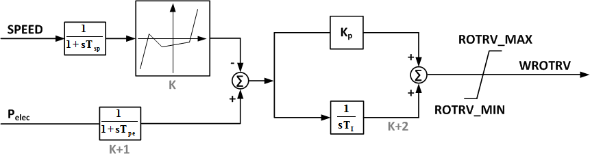
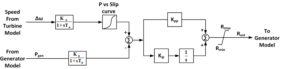
Rotor Resistance Control Model (WT2E)
The Rotor Resistance Control WT2E model was developed based on pre-computed resistance-slip table. This model uses the machine rotor speed and electrical power as inputs and calculates the portion of the available rotor external resistance to be added to the internal rotor resistance.
| Input data for WT2E | ||
|---|---|---|
| CONs | Default Value | Description |
| J | 0.05 | TSP, Rotor speed filter time constant, sec. |
| J+1 | 0.05 | Tpe, power filter time constant, sec. |
| J+2 | 1.00 | Ti, PI-controller integrator time constant, sec. |
| J+3 | 1.00 | Kp, PI-controller promotional gain, pu |
| J+4 | 0.99 | ROTRV_MAX, Output MAX limit |
| J+5 | 0.05 | ROTRV_MIN, Output MIN limit |
| STATEs | Description | |
| K | Rotor speed filter | |
| K+1 | Power filter | |
| K+2 | PI integrator | |
- Block Diagram
PSLF
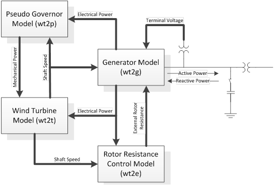
The WT2 modeling package includes 4 main models as follows:
- Generator model wt2g
- Rotor resistance control model for the WT2 Generic Wind Model wt2e
- Two mass turbine model for the WT2 Generic Wind Model wt2t
- Pseudo-governor model for the WT2 Generic Wind Model wt2p
Control input parameters:
- Most of the parameters are given and unique for a specific turbine.
- Available in PSSE [1] and PSLF [2]
- The compensating capacitor is not dynamically modeled but it should be provided and initialized from load flow data.
- WIND PLANT SPECIFIC ADJUSTMENT:
- Plant Size
- Dual mass versus single mass
Induction Generator Model (wt2g)
The Generator model wt2g is a modified standard model of the induction machine with the logic for calculating the external rotor resistance at initialization and some other provisions included. Actually, this is the slightly modified model of the wound rotor induction machine.
| Input data for wt2g | ||
|---|---|---|
| Variable | Default Value | Description |
| Ls | 6.966 | Synchronous reactance, p.u. |
| Lp | 0.301 | Transient reactance, p.u. |
| L1 | 0.126 | Stator leakage reactance, p.u. |
| Ra | 0.004 | Stator resistance, p.u. |
| Tpo | 4.230 | Transient rotor time constant, sec. |
| Se1 | 0.030 | Saturation factor at 1 p.u. flux |
| Se2 | 0.290 | Saturation factor at 1.2 p.u. flux |
| Spdrot | 1.040 | Initial electrical rotor speed, p.u. of system frequency |
| Acc | 0.0 | Acceleration factor for initialization |
| Output data for wt2g | ||
| Record Level | Variable | Description |
| 1 | Spd | Generator speed, p.u. |
| 1 | Slip | Rotor slip, Hz. |
| 1 | Vt | Terminal voltage, p.u. |
| 2 | Pg | Real power output, MW |
| 2 | Qnet | Net reactive power output, MVAr |
| 2 | Qgen | Generator reactive power output, MVAr |
| 2 | Qcap | Capacitor reactive power output, MW |
| 3 | R2ex | External rotor resistance, p.u. |
| 3 | pm | Mechanical power, MW |
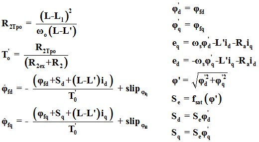
- Electrical Equations
Turbine Model (wt2t)
The turbine wt2t model uses the two-mass representation of the wind turbine shaft drive train. It calculates the speed deviations of the rotor on the machine and on the blade sides. By setting the turbine inertia fraction Htfrac = 0 the model can be switched to a conventional single mass representation.
| Input data for wt2t | ||
|---|---|---|
| Variable | Default Value | Description |
| H | 3.46 | Total inertia constant, MW-sec/MVA |
| D | 0.0 | Damping factor, p.u. P / p.u. speed |
| Optional two-mass model: | ||
| Htfrac | 0.81 | Turbine inertia fraction (Ht / H) |
| Freq1 | 1.50 | First shaft torsional resonant frequency, Hz |
| Dshaft | 0.30 | Shaft damping factor, p.u. P / p.u. speed |
| Output data for wt2t | ||
| Record Level | Variable | Description |
| 1 | spd | Generator speed, p.u. (ω) |
| 2 | wtur | Turbine speed, p.u. in two-mass model (ωt) |
- Block Diagram (Single Mass)
.png)
- Block Diagram (Dual Mass)
.png)
Pseudo Governor Model (wt2p)
The pseudo governor model wt2p is an attempt to simplify and generalize calculation of the aero-torque. This model was designed and developed after thorough investigation of aero-dynamic characteristics and pitch control of several vendor specific wind turbines. Finally the arrangement shown below was suggested. The model uses two inputs, one in terms of the blade rotor speed deviation and another in terms of the real power at the machine terminals. These two inputs combined together are processed by a PI controller with non-wind-up limits. The filtered output is the mechanical power on the rotor blade side which is used by the wt2t model.
| Input data for wt2p | ||
|---|---|---|
| Variable | Default Value | Description |
| Tpe | 0.10 | Time constant, sec. |
| Kdroop | 0.015 | Droop gain |
| Kp | 20 | PI proportional gain |
| Ki | 1.0 | PI integral gain |
| Pimax | 1.00 | PI output maximum limit, p.u. |
| Pimin | 0.25 | PI output minimum limit, p.u. |
| T1 | 0.10 | Time constant, sec. |
| T2 | 0.10 | Time constant, sec. |
| Output data for wt2p | ||
| Record Level | Variable | Description |
| 1 | pm | Mechanical power, MW (Pmech) |
- Block Diagram
Rotor Resistance Control Model (wt2e)
The Rotor Resistance Control wt2e model was developed based on pre-computed resistance-slip table.
| Input data for wt2e | ||
|---|---|---|
| Variable | Default Value | Description |
| Tw | 0.05 | Δω Time constant, sec. |
| Kw | 1.00 | Δω gain |
| Tp | 0.05 | P time constant, sec. |
| Kp | 1.00 | P gain |
| Kpp | 0.01 | Proportional gain |
| Kip | 0.01 | Integral gain |
| Rmax | 0.0977 | Maximum external rotor resistance, p.u. |
| Rmin | 0.0061 | Minimum externals rotor resistance, p.u. |
| Slip1 | 0.00 | Slip point 1 in Power vs. Slip curve, p.u. |
| Slip2 | 0.0054 | Slip point 2 in Power vs. Slip curve, p.u. |
| Slip3 | 0.0200 | Slip point 3 in Power vs. Slip curve, p.u. |
| Slip4 | 0.0400 | Slip point 4 in Power vs. Slip curve, p.u. |
| Slip5 | 0.100 | Slip point 5 in Power vs. Slip curve, p.u. |
| Powr1 | 0.00 | Power point 1 in Power vs. Slip curve, p.u. |
| Powr2 | 0.0217 | Power point 2 in Power vs. Slip curve, p.u. |
| Powr3 | 0.8988 | Power point 3 in Power vs. Slip curve, p.u. |
| Powr4 | 0.900 | Power point 4 in Power vs. Slip curve, p.u. |
| Powr5 | 0.905 | Power point 5 in Power vs. Slip curve, p.u. |
| Output data for wt2e | ||
| Record Level | Variable | Description |
| 1 | Rext | External rotor resistance, p.u. |
- Block Diagram
References
- ↑ 1.0 1.1 1.2 1.3 Siemens Energy, Inc., PSSE Wind Model Library, Schenectady, NY, 2009.
- ↑ 2.0 2.1 2.2 GE Energy, PSLF Version 17.0_07 User’s Manual, Schenectady, NY, 2010.
- ↑ Working Group Joint Report – WECC Working Group on Dynamic Performance of Wind Power Generation & IEEE Working Group on Dynamic Performance of Wind Power Generation of the IEEE PES Power Stability Controls Subcommittee of the IEEE PES Power System Dynamic Performance Committee, “Description and Technical Specifications for Generic WTG Models – A Status Report.”