
The WT3 WECC generic wind turbine stability model was developed to simulate performance of a wind turbine employing a doubly fed induction generator (DFIG) with the active control by a power converter connected to the rotor terminals. WT3 is currently implemented in Siemens PTI – Power System Simulation for Engineering (PSSE [1]), GE – Positive Sequence Load Flow (PSLF [2]), and other simulation programs used in WECC.
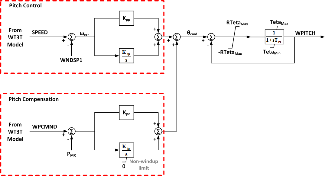
The model is based on on the detailed GE’s wind turbine model [3] [4] and consists of four components: generator/converter, converter control, wind turbine, and pitch control. Several simplifications were made to the GE WTG model, for instance: the active power control and GE’s WindINERTIA control were excluded. In the generic Type 3 generator/converter model, the flux dynamics are eliminated to reflect the rapid response of the converter to the higher level commands from the electrical controls. The model also includes a Low Voltage Power Logic (which can be bypassed) used to limit the real current command during and immediately following sustained faults. The converter control model consists of two components: the reactive and active power control modules. The converter control dictates the active and reactive power to be delivered to the system via the current and voltage commands to the generator, Ipcmd, and Eqcmd, respectively. The reactive power order, Qord, can either be held constant or be computed by a separate model, the Wind Plant Reactive Power Control Emulator, or the power factor regulator. The Wind Plant Reactive Power Control Emulation represents a simplified equivalent of the supervisory VAr controller portion of the entire wind farm management system. The active power order is derived from the generator power and speed. The speed reference, ωref, is obtained from a turbine speed setpoint vs. power output f(Pgen) curve. A very simplified aerodynamic model is used in the Type 3 generic WTG model. This model does not require the representation of the power coefficient curve and is based on the results of the investigation reported in [5]. In the pitch controller model, the blade position actuators are rate limited and there is a time constant associated with the translation of blade angle to mechanical output. The pitch control consists of two PI controllers that act on the speed and power errors.[6]
Contents
PSSE
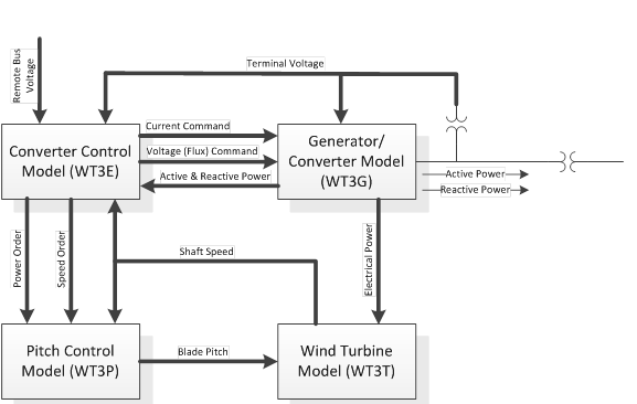
The WT3 modeling package includes 4 main models as follows:
- Generator/Converter Model WT3G
- Electrical control model (converter control) for the Generic Wind Model WT3E
- Mechanical control (wind turbine) for the WT3 Generic Wind Model WT3T
- Pitch control model for the WT3 Generic Wind Model WT3P
Control input parameters:
- Most of the parameters are given and unique for a specific turbine.
WIND PLANT SPECIFIC ADJUSTMENTS:
- varflg and vltflg are flags that must be set by the user based on the setting defined for each WPP to be included in the case study.
- Fn = fraction of WTG on the wind plant that are on-line. Used only for VAR control gain adjustment
- PFAref = initialized from load flow data
- Vc is the controlled bus specified within the module WT3E. It can be terminal voltage or remote bus voltage or fictitious remote bus voltage.
- Xc is a fictitious reactance used to compute the voltage drop to offset the reference voltage of a known bus voltage Vrfq and a known branch current Ireg. (Vc=|Vrfq − jXc Ireg|)
- Vw > 1.0 p.u. will be used to initialize pitch angle.
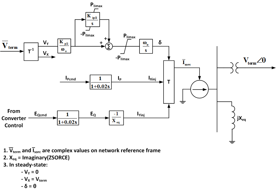
Generator/Converter Model (WT3G)
This model (WT3G) is an equivalent of the generator and the field converter and provides the interface between the WTG and the network. Unlike a conventional generator model, it contains no mechanical state variables for the machine rotor – these are included in the turbine model (WT3T). Further, unlike conventional generator models, all of the flux dynamics have been eliminated to reflect the rapid response to the higher level commands from the electrical controls through the converter. The net result is an algebraic, controlled-current source that computes the required injected current into the network in response to the flux and active current commands from the electrical control model. For modeling an aggregation of several (N) WTGs, MVAb must equal N times the MVA rating of a single WTG. There are two different generator/converter models available, namely WT3G1 and WT3G2. The WT3G2 model, which is recommended for new dynamic setups, includes improvements in the original WT3G1. The original WT3G1 model is being retained for reasons of backward compatibility.
| Input data for WT3G1 | ||
|---|---|---|
| CONs | Default Value | Description |
| J | 0.80 | Xeq, Equivalent reactance for current injection, pu |
| J+1 | 30.0 | Kpll, PLL first integrator gain |
| J+2 | 0.0 | Kipll, PLL second integrator gain |
| J+3 | 0.10 | Pllmax, PLL maximum limit |
| J+4 | 1.50 | Prated, Turbine MW rating |
| STATEs | Description | |
| K | Converter lag for Ipcmd | |
| K+1 | Converter lag for Eqcmd | |
| K+2 | PLL first integrator | |
| K+3 | PLL second integrator | |
| VARs | Description | |
| L | Vx, Real component of Vterm in generator ref. frame | |
| L+1 | VY, Imaginary component of Vterm in generator ref. frame | |
| L+2 | Ixinj, Active component of the injected current | |
| L+3 | Iyinj, Reactive component of the injected current | |
| ICONs | Description | |
| M | Number of lumped wind turbines | |
- Block Diagram (WT3G1)
| Input data for WT3G2 | ||
|---|---|---|
| CONs | Default Value | Description |
| J | 0.20 | Tiqcmd, Converter time constant for IQcmd |
| J+1 | 0.0 | Tipcmd, Converter time constant for IPcmd |
| J+2 | 0.0 | KPLL, PLL gain |
| J+3 | 0.0 | KIPLL, PLL integrator gain |
| J+4 | 0.10 | PLLMAX, PLL max. limit |
| J+5 | 1.50 | Prated |
| J+6 | 0.50 | VLVPL1, LVPL voltage 1 Low voltage power logic |
| J+7 | 0.90 | VLVPL2, LVPL voltage 2 |
| J+8 | 1.0 | GLVPL, LVPL gain |
| J+9 | 1.20 | VHVRCR, High Voltage Reactive Current (HVRC) logic, pu voltage |
| J+10 | 2.0 | CURHVRCR, HVRC logic, current (pu) |
| J+11 | 5.0 | RIp_LVPL, Rate of active current change |
| J+12 | 0.02 | T_LVPL, Voltage sensor for LVPL, second |
| STATEs | Description | |
| K | Converter lag for Ipcmd | |
| K+1 | Converter lag for Iqcmd | |
| K+2 | PLL first integrator | |
| K+3 | PLL second integrator | |
| K+4 | Voltage sensor for LVPL | |
| VARs | Description | |
| L | deltaQ, overvoltage correction factor | |
| ICONs | Description | |
| M | Number of lumped wind turbines | |
- Block Diagram (WT3G2)
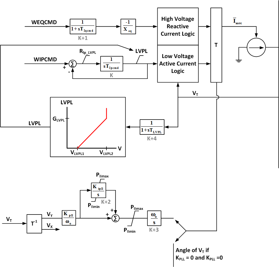
“High-voltage reactive current management” and “low-voltage active current management” represent logic associated with the dynamic model and the ac network solution. They actual implementation of this logic may be software dependent.
Turbine Model (WT3T)
The turbine WT3T model uses the two-mass representation of the wind turbine shaft drive train. It calculates the speed deviations of the rotor on the machine and on the blade sides. By setting the turbine inertia fraction Htfrac = 0 the model can be switched to a conventional single mass representation.
| Input data for WT3T | ||
|---|---|---|
| CONs | Default Value | Description |
| J | 1.25 | VW, Initial wind, pu of rated wind speed |
| J+1 | 4.95 | H, Total inertia constant, sec |
| J+2 | 0.0 | DAMP, Machine damping factor, pu P/pu speed |
| J+3 | 0.7e-02 | Kaero, Aerodynamic gain factor |
| J+4 | 21.98 | Theta2, Blade pitch at twice rated wind speed, deg. |
| J+5 | 0.0 | Htfrac, Turbine inertia fraction (Hturb/H)1 |
| J+6 | 1.8 | Freq1, First shaft torsional resonant frequency, Hz |
| J+7 | 1.5 | Dshaft, Shaft damping factor (pu) |
| STATEs | Description | |
| K | Shaft twist angle, rad. | |
| K+1 | Turbine rotor speed deviation, pu | |
| K+2 | Generator speed deviation, pu | |
| K+3 | Generator rotor angle deviation, pu | |
| VARs | Description | |
| L | Paero on the rotor blade side, pu | |
| L+1 | Initial rotor slip | |
| L+2 | Initial internal angle | |
| L+3 | Initial pitch angle | |
| L+4 | Paero initial | |
1To simulate one-mass mechanical system, set Htfrac = 0. To simulate two-mass mechanical system, set Htfrac as 0 < Htfrac < 1
- Block Diagram (Dual Mass)
.png)
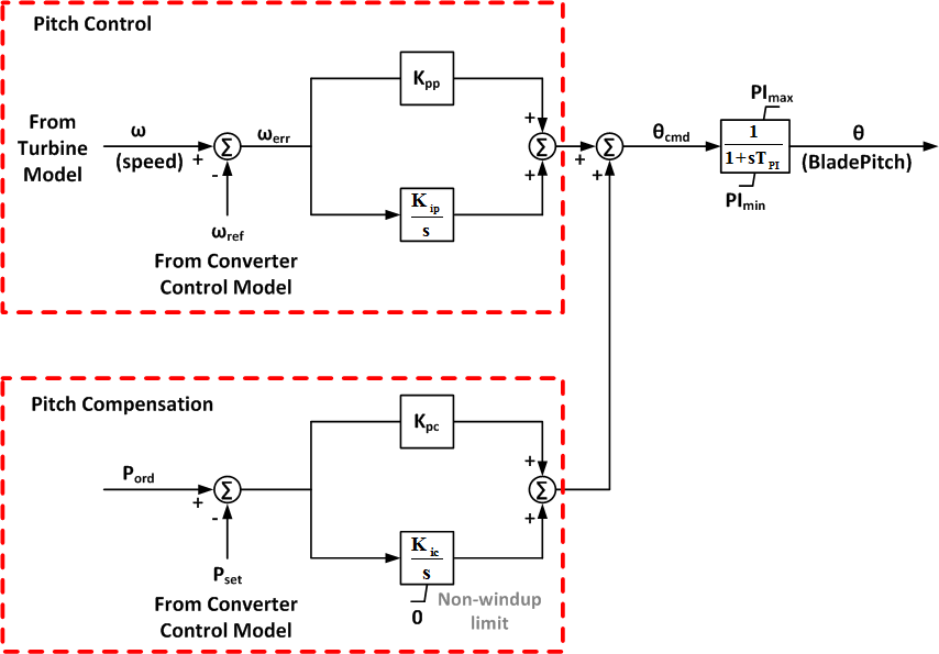
Pitch Control Model (WT3P)
| Input data for WT3P | ||
|---|---|---|
| CONs | Default Value | Description |
| J | 0.30 | Tp, Blade response time constant |
| J+1 | 150.0 | Kpp, Proportional gain of PI regulator (pu) |
| J+2 | 25.0 | Kip, Integrator gain of PI regulator (pu) |
| J+3 | 3.0 | Kpc, Proportional gain of the compensator (pu) |
| J+4 | 30.0 | Kic, Integrator gain of the compensator (pu) |
| J+5 | 0.0 | TetaMin, Lower pitch angle limit (degrees) |
| J+6 | 27.0 | TetaMax, Upper pitch angle limit (degrees) |
| J+7 | 10.0 | RTetaMax, Upper pitch angle rate limit (degrees/sec) |
| J+8 | 1.0 | PMX, Power reference, pu on MBASE |
| STATEs | Description | |
| K | Output lag | |
| K+1 | Pitch control | |
| K+2 | Pitch compensation | |
- Block Diagram
Converter Control Model (WT3E)
This model (WT3E) dictates the active and reactive power to be delivered to the system. The reactive controls including the emulation of the centralized Wind Plant reactive power controller is shown below. The switch, VARFLG, provides for 3 modes of control: constant reactive power, constant power factor angle, or voltage regulation by a wind plant reactive power controller. The switch, VLTFLG, provides for bypassing the closed loop terminal voltage regulator, which is not used in all implementations and currently is always set to 1. The non-linear function, f(Pelec), is used to model the desired WTG speed as a function the power level. The input data for this function are values of the desired speed at several levels of power output, with linear interpolation to be used between specified values. The electrical control model WT3E can be used with WT3G1 as well as with the improved WT3G2 models. When WT3E is used with the WT3G1 model, it is recommended that ICON(M+2) be set to 1, and when used with WT3G2, the ICON(M+2) be set to 2.
| Input data for WT3E | ||
|---|---|---|
| CONs | Default Value | Description |
| J | 0.15 | Tfv, Filter time constant in voltage regulator (sec) |
| J+1 | 18.0 | Kpv, Proportional gain in voltage regulator (pu) |
| J+2 | 5.0 | Kiv, Integrator gain in voltage regulator (pu) |
| J+3 | 0.0 | Xc, Line drop compensation reactance (pu) |
| J+4 | 0.05 | TFP, Filter time constant in torque regulator |
| J+5 | 3.0 | Kpp, Proportional gain in torque regulator (pu) |
| J+6 | 0.60 | KIP, Integrator gain in torque regulator (pu) |
| J+7 | 1.12 | PMX, Max limit in torque regulator (pu) |
| J+8 | 0.10 | PMN, Min limit in torque regulator (pu) |
| J+9 | 0.296 | QMX, Max limit in voltage regulator (pu) |
| J+10 | -0.436 | QMN, Min limit in voltage regulator (pu) |
| J+11 | 1.10 | IPMAX, Max active current limit |
| J+12 | 0.05 | TRV, Voltage sensor time constant |
| J+13 | 0.45 | RPMX, Max power order derivative |
| J+14 | -0.45 | RPMN, Min power order derivative |
| J+15 | 5.0 | T_Power, Power filter time constant |
| J+16 | 0.05 | Kqi, MVAR/Voltage gain |
| J+17 | 0.90 | VMINCL, Min voltage limit |
| J+18 | 1.20 | VMAXCL, Max voltage limit |
| J+19 | 40.0 | Kqv, Voltage/MVAR gain |
| J+20 | -0.50 | XIQmin |
| J+21 | 0.40 | XIQmax |
| J+22 | 0.05 | Tv, Lag time constant in WindVar controller |
| J+23 | 0.05 | Tp, Pelec filter in fast PF controller |
| J+24 | 1.0 | Fn, A portion of online wind turbines |
| J+25 | 0.69 | ωPmin, Shaft speed at Pmin (pu) |
| J+26 | 0.78 | ωP20, Shaft speed at 20% rated power (pu) |
| J+27 | 0.98 | ωP40, Shaft speed at 40% rated power (pu) |
| J+28 | 1.12 | ωP60, Shaft speed at 60% rated power (pu) |
| J+29 | 0.74 | ωPmin, Minimum power for operating at P100 speed (pu) |
| J+30 | 1.20 | ωP100, Shaft speed at 100% rated power (pu) |
| STATEs | Description | |
| K | Filter in voltage regulator | |
| K+1 | Integrator in voltage regulator | |
| K+2 | Filter in torque regulator | |
| K+3 | Integrator in torque regulator | |
| K+4 | Voltage sensor | |
| K+5 | Power filter | |
| K+6 | MVAR/Vref integrator | |
| K+7 | Verror/internal machine voltage integrator | |
| K+8 | Lag of the WindVar controller | |
| K+9 | Input filter of Pelec for PF fast controller | |
| VARs | Description | |
| L | Remote bus ref voltage | |
| L+1 | MVAR order from MVAR emulator | |
| L+2 | Q reference if PFAFLG=0 & VARFLG=0 | |
| L+3 | PF angle reference if PFAFLG=1 | |
| L+4 | Storage of MW for computation of compensated voltage | |
| L+5 | Storage of MVAR for computation of compensated voltage | |
| L+6 | Storage of MVA for computation of compensated voltage | |
| ICONs | Description | |
| M | Remote bus # for voltage control; 0 for local voltage control | |
| M+1 | VARFLG:
|
|
| M+2 | VLTFLG:
|
|
| M+3 | From bus of the interconnection transformer | |
| M+4 | To bus of the interconnection transformer | |
| M+5 | Interconnection transformer ID | |
- Block Diagram

PSLF

The WT3 modeling package includes 3 main models as follows:
- Generator/Converter Model wt3g
- Converter Control Model for the Generic Wind Model wt3e
- Two mass turbine model for the wt3 Generic Wind Model wt3t
- Pseudo-governor model for the wt3 Generic Wind Model wt3p
Control input parameters:
- Most of the parameters are given and unique for a specific turbine.
WIND PLANT SPECIFIC ADJUSTMENTS:
- varflg and vltflg are flags that must be set by the user based on the setting defined for each WPP to be included in the case study.
- Fn = fraction of WTG on the wind plant that are on-line. Used only for VAR control gain adjustment
- PFAref = initialized from load flow data
- Vc is the controlled bus specified within the module wt3e. It can be terminal voltage or remote bus voltage or fictitious remote bus voltage.
- Xc is a fictitious reactance used to compute the voltage drop to offset the reference voltage of a known bus voltage Vrfq and a known branch current Ireg. (Vc=|Vrfq − jXc Ireg|)
- Vw > 1.0 p.u. will be used to initialize pitch angle.
Generator/Converter Model (wt3g)
This model (wt3g) is an equivalent of the generator and the field converter and provides the interface between the WTG and the network. Unlike a conventional generator model, it contains no mechanical state variables for the machine rotor – these are included in the turbine model (wt3t). Further, unlike conventional generator models, all of the flux dynamics have been eliminated to reflect the rapid response to the higher level commands from the electrical controls through the converter. The net result is an algebraic, controlled-current source that computes the required injected current into the network in response to the flux and active current commands from the electrical control model. For modeling an aggregation of several (N) WTGs, MVAb must equal N times the MVA rating of a single WTG.
| Input data for wt3g | ||
|---|---|---|
| Variable | Default Value | Description |
| Lpp | 0.8 | Generator effective reactance, p.u. on gen. MVA base |
| Lvplsw | 1.0 | Connect (1) / disconnect (0) Low Volt. Power Logic switch |
| Rrpwr | 10.0 | LVPL ramp rate limit, p.u. |
| Brkpt | 0.90 | LVPL characteristic breakpoint, p.u. |
| Zerox | 0.50 | LVPL characteristic zero crossing, p.u. |
| Lvpl1 | 1.22 | LVPL breakpoint, p.u. |
| Volim | 1.20 | Voltage limit assoc. with the high voltage reactive current management, p.u.1 |
| Lvpnt1 | 0.80 | High voltage point for low voltage active current management, p.u.2 |
| Lvpnt0 | 0.40 | Low voltage point for low voltage active current management, p.u.2 |
| Output data for wt3g | ||
| Record Level | Variable | Description |
| 1 | Vt | Terminal voltage, pu |
| 1 | Pg | Electrical power, MW |
| 1 | Qg | Reactive power, MVAr |
| 2 | Ipcd | Active current command (I”pcmd), p.u. |
| 2 | Eqcd | Flux command (E”qcmd), p.u. |
| 2 | Ip | Active current (Pgen/Vt), p.u. |
| 2 | Iq | Reactive current (Qgen/Vt), p.u. |
| 2 | iplv | Final active current command after LVPL, p.u. |
1The ‘High Voltage Reactive Current Management” block limits the reactive current injected into the network equations such that the terminal voltage of the machine does not exceeds Volim of nominal, as long as the converter is within current limits.
2The “Low Voltage Active Current Management” block is designed to capture the characteristic of active power under very low voltage scenarios. This low voltage limit is designed to reduce active current in a linear fashion. The linear function is somewhat like that shown in “low voltage power logic” block, but starts at Lvpnt1 p.u. voltage and declines to zero at Lvpnt0 p.u. voltage.
- Block Diagram
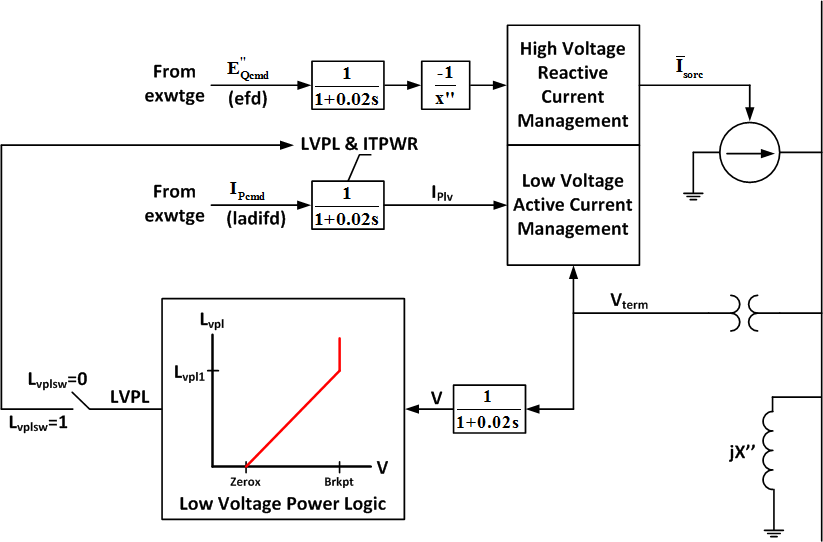
“High-voltage reactive current management” and “low-voltage active current management” represent logic associated with the dynamic model and the ac network solution. They actual implementation of this logic may be software dependent.
Turbine Model (wt3t)
The turbine wt3t model uses the two-mass representation of the wind turbine shaft drive train. It calculates the speed deviations of the rotor on the machine and on the blade sides. By setting the turbine inertia fraction Htfrac = 0 the model can be switched to a conventional single mass representation.
| Input data for wt3t | ||
|---|---|---|
| Variable | Default Value | Description |
| Vw | Initial wind speed, p.u. of rated wind speed | |
| H | 4.94 | Total inertia constant, MW-sec/MVA |
| D | 0.0 | Damping factor, p.u. P / p.u. speed |
| Kaero | 0.007 | Aerodynamic gain factor |
| Theta2 | 21.98 | Blade pitch at twice rated wind speed, deg. |
| Optional two-mass model: | ||
| Htfrac | 0.875 | Turbine inertia fraction (Ht / H) |
| Freq1 | 1.80 | First shaft torsional resonant frequency, Hz |
| Dshaft | 1.50 | Shaft damping factor, p.u. P / p.u. speed |
| Output data for wt3t | ||
| Record Level | Variable | Description |
| 1 | spd | Generator speed, p.u. (ω) |
| 1 | pm | Mechanical power, MW (Pmech) |
| 2 | wtur | Turbine speed, p.u. in two-mass model (ωt) |
- Block Diagram (Single Mass)
.png)
- Block Diagram (Dual Mass)
.png)
Pitch Control Model (wt3p)
| Input data for wt3p | ||
|---|---|---|
| Variable | Default Value | Description |
| Kpp | 150.0 | Pitch control proportional gain, deg./ p.u. speed |
| Kip | 25.0 | Pitch control integral gain, deg./ (p.u. speed-sec.) |
| Kpc | 3.0 | Pitch compensator proportional gain, deg./ p.u. P |
| Kic | 30.0 | Pitch compensator integral gain, deg./ (p.u. P-sec.) |
| Pimax | 27.0 | Maximum pitch angle, deg. |
| Pimin | 0.0 | Minimum pitch angle, deg. |
| Pirat | 10.0 | Pitch rate limit, deg./sec. |
| Tpi | 0.30 | Blade response time constant, sec. |
| Pset | 1.0 | Power set point, p.u. |
| Output data for wt3p | ||
| Record Level | Variable | Description |
| 1 | Wref | Speed reference, p.u. (ωref) |
| 1 | Pitc | Blade pitch, deg. (θ) |
| 1 | spde | Speed error, p.u. (ωerr) |
- Block Diagram
Converter Control Model (wt3e)
This model (wt3e) dictates the active and reactive power to be delivered to the system. The reactive controls including the emulation of the centralized Wind Plant reactive power controller is shown below. The switch, VARFLG, provides for 3 modes of control: constant reactive power, constant power factor angle, or voltage regulation by a wind plant reactive power controller. The switch, VLTFLG, provides for bypassing the closed loop terminal voltage regulator, which is not used in all implementations and currently is always set to 1. The non-linear function, f(Pelec), is used to model the desired WTG speed as a function the power level. The input data for this function are values of the desired speed at several levels of power output, with linear interpolation to be used between specified values.
| Input data for wt3e | ||
|---|---|---|
| Variable | Default Value | Description |
| varflg | 0.00 | 0 = Constant Q cntl 1 = Use Wind Plant reactive power cntrl -1 = Constant power factor control |
| vltflg | 1.00 | 1 = Use closed loop terminal voltage control 0 = Bypass closed loop terminal voltage control |
| Tsp | 5.00 | Speed reference lag (sec) |
| Kptrq | 3.00 | Torque control proportional gain (p.u. P) |
| Kitrq | 0.60 | Torque control integral gain (p.u. P / sec) |
| Tpc | 0.05 | Power control lag (sec) |
| Pmax | 1.12 | Maximum power order (p.u.) |
| Pmin | 0.04 | Minimum power order (p.u.) |
| Pwrat | 0.45 | Power order rate limit (p.u./sec) |
| Ipmax | 1.10 | Maximum reactive current order, (p.u. of rated current) |
| Wpmin | 0.69 | Shaft speed at Pmin (p.u.) |
| Wp20 | 0.78 | Shaft speed at 20% rated power (p.u.) |
| Wp40 | 0.98 | Shaft speed at 40% rated power (p.u.) |
| Wp60 | 1.12 | Shaft speed at 60% rated power (p.u.) |
| Pwp100 | 0.74 | Minimum power for operating at wp100 speed (p.u.) |
| Wp100 | 1.20 | Shaft speed at rated power (p.u.) |
| Kqi | 0.10 | Reactive control gain (p.u. V/p.u. Q sec) |
| Kqv | 40.0 | Terminal voltage control gain, (p.u. V/p.u. V) |
| Qmax | 0.436 | Maximum reactive power limit (p.u.) |
| Qmin | -0.436 | Minimum reactive power limit (p.u.) |
| Vmax | 1.10 | Maximum voltage limit (p.u.) |
| Vmin | 0.90 | Minimum voltage limit (p.u.) |
| XIqmax | 1.45 | Terminal voltage regulator maximum limit (p.u.) |
| XIqmin | 0.50 | Terminal voltage regulator minimum limit (p.u.) |
| Tp | 0.05 | Power factor control filter time constant (sec) |
| Xc | 0.00 | Compensating reactance for voltage control (p.u.) |
| Tr | 0.02 | Voltage transducer time constant (sec) |
| Fn | 1.00 | Fraction of WTG in Wind Plant that are on-line |
| Kiv | 5.00 | Integral gain (p.u. Q/p.u. V sec) |
| Kpv | 18.0 | Proportional gain (p.u. Q/p.u. V ) |
| Tv | 0.05 | Proportional path time constant (sec) |
| Tc | 0.15 | Communication lag (sec) |
| Output data for wt3e | ||
| Record Level | Variable | Description |
| 1 | Pord | Power controller output, p.u. (Pord) |
| 1 | Icmd | Current command to generator, p.u. (Ip cmd) |
| 1 | Ecmd | Voltage (flux) command to generator, p.u. (Eq cmd) |
| 2 | Qord | Reactive power order, p.u. (Qord) |
| 2 | Vref | Local voltage reference, p.u. (Vref) |
| 2 | Vrfq | Reactive power control emulator ref. voltage, p.u. (Vrfq) |
| 2 | Vreg | Reactive power control emulator regulated voltage, p.u. (Vc) |
- Block Diagram (Reactive Power Control)
.png)
- Block Diagram (Reactive Power Torque Control)
.png)
References
- ↑ Siemens Energy, Inc., PSSE Wind Model Library, Schenectady, NY, 2009.
- ↑ GE Energy, PSLF Version 17.0_07 User’s Manual, Schenectady, NY, 2010.
- ↑ Nicholas W. Miller, Juan J. Sanchez-Gasca, William W. Price, Robert W. Delmerico, “Dynamic Modeling of GE 1.5 and 3.6 MW Wind Turbine-Generators for Stability Simulations”, Proc. Power Engineering Society General Meeting 2003. Toronto, Ontario. July 2003.
- ↑ K. Clark, N. W. Miller, J. J. Sanchez-Gasca, Modeling of GE Wind Turbine-Generators for Grid Studies, Version 4.5, April 2010, General Electric International, Inc.
- ↑ W. W. Price, J.J. Sanchez-Gasca, “Simplified Wind Turbine Generator Aerodynamic Models for Transient Stability Studies”, Proc. IEEE PES 2006 Power Systems Conference and Exposition (PSCE), Oct. 29-Nov. 1, 2006, Atlanta, GA, pp. 986-992.
- ↑ Working Group Joint Report – WECC Working Group on Dynamic Performance of Wind Power Generation & IEEE Working Group on Dynamic Performance of Wind Power Generation of the IEEE PES Power Stability Controls Subcommittee of the IEEE PES Power System Dynamic Performance Committee, “Description and Technical Specifications for Generic WTG Models – A Status Report.”