
The WT4 WECC generic wind turbine dynamic stability model was developed to simulate performance of a wind turbine employing a generator connected to the grid via the power converter (Type IV). WT4 is currently implemented in Siemens PTI – Power System Simulation for Engineering (PSSE [1]), GE – Positive Sequence Load Flow (PSLF [2]), and other simulation programs used in WECC.
This model consists of three components: generator/converter, converter control, and wind turbine. The model is based on GE’s wind turbine model.[3] The generator model is very similar to the Type 3 generator model. The main difference is that the model takes as inputs both reactive and active current commands. The converter control model dictates the active and reactive power to be delivered to the system. The overall structure of the controller is somewhat similar to the Type 3 WTG reactive power control model but it includes logic to determine the current limits. The objective of the converter current limit is to prevent the combination of the real and reactive currents from exceeding converter capability. Depending upon the value of a user-specified P, Q priority flag, either real or reactive power has priority. This flag is dependent upon the equipment features selected, and is normally dictated by the host system grid code. The Type 4 generic WTG includes a simplified turbine model.[4]
Contents
PSSE
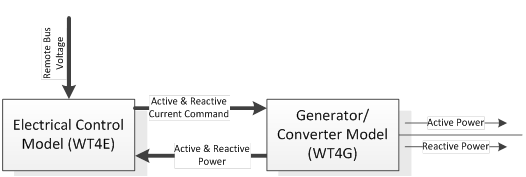
The WT4 modeling package includes 3 main models as follows:
- Generator/Converter Model WT4G
- Converter Control Model for the Generic Wind Model WT4E
Control input parameters:
- Most of the parameters are given and unique for a specific turbine.
WIND PLANT SPECIFIC ADJUSTMENTS:
- varflg and vltflg are flags that must be set by the user based on the setting defined for each WPP to be included in the case study.
- Fn = fraction of WTG on the wind plant that are on-line. Used only for VAR control gain adjustment
- PFAref = initialized from load flow data
- Refer to Type-3 description of Remote Control Voltage Vc and Vrfq
Generator/Converter Model (WT4G)
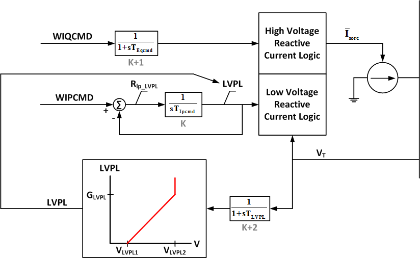
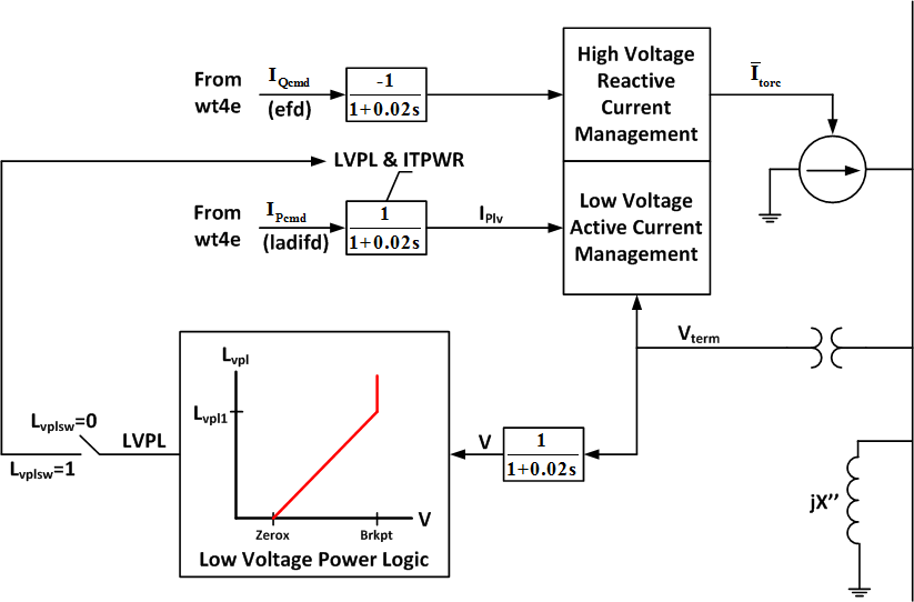
This model (WT4G) is an equivalent of the generator and the field converter and provides the interface between the WTG and the network. Unlike a conventional generator model, it contains no mechanical state variables. The model calculates the current injection to the grid based on filtered active and reactive power commands from the electrical control module. Both components of the injected current are processed under the high/low voltage conditions by means of a special logic.
| Input data for WT4G | ||
|---|---|---|
| CONs | Default Value | Description |
| J | 0.02 | TIQCmd, Converter time constant for IQcmd |
| J+1 | 0.02 | TIPCmd, Converter time constant for IPcmd |
| J+2 | 0.40 | VLVPL1, LVPL voltage 1 (Low voltage power logic) |
| J+3 | 0.90 | VLVPL2, LVPL voltage 2 |
| J+4 | 1.11 | GLVPL, LVPL gain |
| J+5 | 1.20 | VHVRCR, HVRCR voltage (High voltage reactive current limiter) |
| J+6 | 2.00 | CURHVRCR, HVRCR current (Max. reactive current at VHVRCR) |
| J+7 | 2.00 | RIp_LVPL, Rate of LVACR active current change |
| J+8 | 0.02 | T_LVPL, Voltage sensor for LVACR time constant |
| STATEs | Description | |
| K | Converter lag for Ipcmd | |
| K+1 | Converter lag for Eqcmd | |
| K+2 | Voltage sensor for LVACR | |
| VARs | Description | |
| L | Previous Vterm magnitude | |
| L+1 | VAACC, previous Vterm angle | |
| L+2 | deltaQ, overvoltage correction factor | |
- Block Diagram
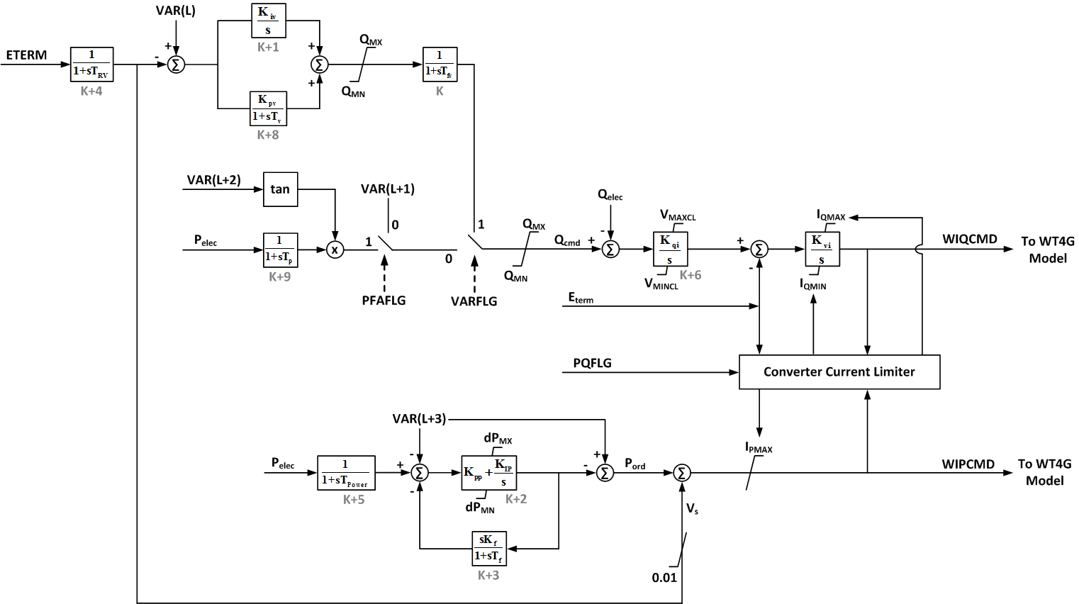
Electrical Control Model (WT4E)
This model (WT4E) is an equivalent of the controller for the power converter.
| Input data for WT4E | ||
|---|---|---|
| CONs | Default Value | Description |
| J | 0.15 | Tfv, Filter time constant in voltage regulator (sec) |
| J+1 | 18.0 | KPV, Proportional gain in Voltage regulator(pu) |
| J+2 | 5.00 | KIV, Integrator gain in Voltage regulator (pu) |
| J+3 | 0.05 | Kpp, Proportional gain in Active Power regulator(pu) |
| J+4 | 0.10 | KIP, Integrator gain in Active Power regulator (pu) |
| J+5 | 0.00 | Kf, Rate feedback gain (pu) |
| J+6 | 0.08 | Tf, Rate feedback time constant (sec.) |
| J+7 | 0.47 | QMX, Max limit in Voltage regulator (pu) |
| J+8 | -0.47 | QMN, Min limit in Voltage regulator (pu) |
| J+9 | 1.10 | IPmax, Max active current limit |
| J+10 | 0.00 | TRV, Voltage sensor time constant |
| J+11 | 0.5 | dPMX, Max limit in power PI controller (pu) |
| J+12 | -0.5 | dPMN, Min limit in power PI controller (pu) |
| J+13 | 0.05 | T_Power, Power filter time constant |
| J+14 | 0.10 | KQI, MVAR/Voltage gain |
| J+15 | 0.90 | VMINCL, Min. voltage limit |
| J+16 | 1.10 | VMAXCL, Max. voltage limit |
| J+17 | 120.0 | KVI, Voltage/MVAR Gain |
| J+18 | 0.05 | Tv, Lag time constant in WindVar controller |
| J+19 | 0.05 | Tp, Pelec filter in fast PF controller |
| J+20 | 1.70 | ImaxTD, Converter current limit |
| J+21 | 1.11 | Iphl, Hard active current limit |
| J+22 | 1.11 | Iqhl, Hard reactive current limit |
| STATEs | Description | |
| K | Filter in voltage regulator | |
| K+1 | Integrator in voltage regulator | |
| K+2 | Integrator in active power regulator | |
| K+3 | Active power regulator feedback | |
| K+4 | Voltage sensor | |
| K+5 | Power filter | |
| K+6 | MVAR/Vref integrator | |
| K+7 | Verror/Internal machine voltage integrator | |
| K+8 | Lag of the WindVar controller | |
| K+9 | Input filter of Pelec for PF fast controller | |
| VARs | Description | |
| L | Remote bus ref voltage | |
| L+1 | Q reference if PFAFLG=0 & VARFLG=0 | |
| L+2 | PFangle reference if PFAFLG=1 | |
| L+3 | Power reference | |
| ICONs | Description | |
| M | Remote bus # for voltage control; 0 for local voltage control | |
| M+1 | PFAFLG:
|
|
| M+2 | VARFLG:
if VARFLG=PFAFLG=0 then Qord is provided as a Qref=const |
|
| M+3 | PQFLAG, P/Q priority flag:
|
|
- Block Diagram
PSLF
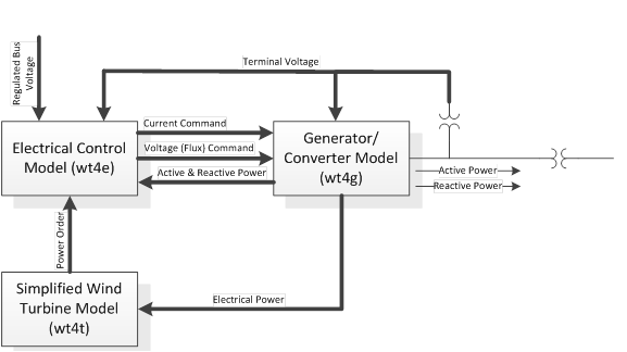
The WT4 modeling package includes 3 main models as follows:
- Generator/Converter Model wt4g
- Converter Control Model for the Generic Wind Model wt4e
- Turbine Model for the Generic Wind Model wt4t
Control input parameters:
- Most of the parameters are given and unique for a specific turbine.
WIND PLANT SPECIFIC ADJUSTMENTS:
- varflg and vltflg are flags that must be set by the user based on the setting defined for each WPP to be included in the case study.
- Fn = fraction of WTG on the wind plant that are on-line. Used only for VAR control gain adjustment
- PFAref = initialized from load flow data
- Refer to Type-3 description of Remote Control Voltage Vc and Vrfq
Generator/Converter Model (wt4g)
This model (wt4g) is an equivalent of the generator and the field converter and provides the interface between the WTG and the network. Unlike a conventional generator model, it contains no mechanical state variables.
| Input data for wt4g | ||
|---|---|---|
| Variable | Default Value | Description |
| Lvplsw | 1.0 | Connect (1) / disconnect (0) Low Volt. Power Logic switch |
| Rrpwr | 10.0 | LVPL ramp rate limit, p.u. |
| Brkpt | 0.90 | LVPL breakpoint, p.u. |
| Zerox | 0.40 | LVPL zero crossing, p.u. |
| Lvpl1 | 1.22 | LVPL breakpoint, p.u. |
| Volim | 1.20 | Voltage limit assoc. with the high voltage reactive current management, p.u.1 |
| Lvpnt1 | 0.80 | High voltage point for low voltage active current management, p.u.2 |
| Lvpnt0 | 0.40 | Low voltage point for low voltage active current management, p.u.2 |
| Output data for wt4g | ||
| Record Level | Variable | Description |
| 1 | Vt | Terminal voltage, pu |
| 1 | Pg | Electrical power, MW |
| 1 | Qg | Reactive power, MVAr |
| 2 | Ipcd | Active current command (Ipcmd), p.u. |
| 2 | iqcd | Reactive current command (Iqcmd), p.u. |
| 2 | Ip | Active current (Pgen/Vt), p.u. |
| 2 | Iq | Reactive current (Qgen/Vt), p.u. |
| 2 | iplv | Final active current command after LVPL, p.u. |
1The ‘High Voltage Reactive Current Management” block limits the reactive current injected into the network equations such that the terminal voltage of the machine never exceeds Volim of nominal, as long as the converter is within current limits.
2The “Low Voltage Active Current Management” block is designed to capture the characteristic of active power under very low voltage scenarios. This low voltage limit is designed to reduce active current in a linear fashion. The linear function is somewhat like that shown in “low voltage power logic” block, but starts at Lvpnt1 p.u. voltage and declines to zero at Lvpnt0 p.u. voltage.
- Block Diagram
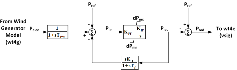
Turbine Model (wt4t)
This model (wt4t) is an equivalent of the simplified wind turbine model.
| Input data for wt4t | ||
|---|---|---|
| Variable | Default Value | Description |
| Tpw | 0.05 | Voltage transducer time constant, p.u. |
| Kpp | 0.08 | PI controller proportional gain, p.u. |
| Kip | 0.10 | PI controller integral gain, p.u. |
| Tf | 0.08 | Rate feedback time constant, p.u. |
| Kf | 0.00 | Rate feedback gain, p.u. |
| dPmx | 0.1 | Maximum PI controller output, p.u. |
| dPmn | -0.1 | Minimum PI controller output, p.u. |
| Output data for wt4t | ||
| Record Level | Variable | Description |
| 1 | Pord | Power order, p.u. |
| 1 | Piin | PI controller input, p.u. |
| 2 | Piou | PI controller output, p.u. |
- Block Diagram
Electrical Control Model (wt4e)
This model (wt4e) is an equivalent of the controller for the power converter.
| Input data for wt4e | ||
|---|---|---|
| Variable | Default Value | Description |
| varflg | 1 | 1 = Qord from WindCONTROL emulation -1 = Qord from vref (i.e., separate model) 0 = Power factor control (pfaflg=1) |
| Kqi | 0.1 | Q control integral gain (see note f) |
| Kvi | 120 | V control integral gain |
| Vmax | 1.1 | Maximum V at regulated bus (p.u.) |
| Vmin | 0.9 | Minimum V at regulated bus (p.u.) |
| Qmax | 0.40 | Maximum Q command (p.u.) |
| Qmin | -0.40 | Minimum Q command (p.u.) |
| Tr | 0.02 | WindCONTROL voltage measurement lag, sec. |
| Tc | 0.15 | Lag between WindCONTROL output and wind turbine, sec. |
| Kpv | 18.0 | WindCONTROL regulator proportional gain (see note g) |
| Kiv | 5.0 | WindCONTROLregulator integral gain (see note g) |
| pfaflg | 0 | 1 = regulate power factor angle 0 = regulate Q |
| fn | 1.0 | fraction of WTGs in wind farm that are on-line |
| Tv | 0.05 | Time constant in proportional path of WindCONTROL emulator, sec. |
| Tpwr | 0.05 | Time constant in power measurement for PFA control (Tp), sec. |
| Iphl | 1.24 | Hard limit on real current, p.u. |
| Iqhl | 1.25 | Hard limit on reactive current, p.u. |
| Pqflag | 0 | 0 = Q priority 1 = P priority |
| Output data for wt4e | ||
| Record Level | Variable | Description |
| 1 | Porx | P order from the turbine control (wndtge), p.u. |
| 1 | Qord | Q order from the WindCONTROL emulator or from a separate model, p.u. |
| 2 | Qcmd | Q command after limits, p.u. |
| 2 | Vref | Local voltage reference, p.u. |
| 2 | Vrfq | WindCONTROL emulator reference voltage, p.u. |
| 2 | Vreg | WindCONTROL emulator regulated voltage, p.u. |
| 2 | Qwv | WindCONTROL emulator PI control output, p.u. |
| 2 | Iqmx | Maximum limit applied to the reactive current order, p.u. |
| 2 | Iqmn | Minimum limit applied to the reactive current order, p.u. |
| 2 | Ipmx | Maximum limit applied to the real current order, p.u. |
| 2 | Iqxv | Voltage dependent reactive current limit (Iqmxv), p.u. |
| 2 | Edbr | Energy absorbed by the braking resistor, p.u. sec |
| 2 | Eerr | Energy error (Edbr-Ebst), p.u. sec |
| 2 | Pdbr | Dynamic breaking resistor power, p.u. |
| 2 | Pdlt | Power order minus electrical power (Porx-Pelec), p.u. |
- Block Diagram (Full Converter WTG Electrical Control_Model)
.png)
- Block Diagram (Converter Current Limit Model)
.png)
References
- ↑ Siemens Energy, Inc., PSSE Wind Model Library, Schenectady, NY, 2009.
- ↑ GE Energy, PSLF Version 17.0_07 User’s Manual, Schenectady, NY, 2010.
- ↑ K. Clark, N. W. Miller, J. J. Sanchez-Gasca, Modeling of GE Wind Turbine-Generators for Grid Studies, Version 4.5, April 2010, General Electric International, Inc.
- ↑ Working Group Joint Report – WECC Working Group on Dynamic Performance of Wind Power Generation & IEEE Working Group on Dynamic Performance of Wind Power Generation of the IEEE PES Power Stability Controls Subcommittee of the IEEE PES Power System Dynamic Performance Committee, “Description and Technical Specifications for Generic WTG Models – A Status Report.”