
Motivation for Grid-Forming Technologies in Germany

To guarantee a safe and stable system operation, the transmission system is designed to withstand different disturbances. In this context the Continental European power system can balance sudden power imbalances of up to 3 GW if it stays interconnected and all grid users comply with grid code requirements. However, more severe disturbances causing cascading line disconnections can result in a system split, as occurred in Europe twice in 2021. This interrupts the power transport between the two subsystems and leads to high power imbalances. Since resulting imbalances can significantly exceed the allocated power reserves of 3 GW, additional measures from the system defense plan are activated automatically depending on the frequency, to prevent a black-out of the system.
The challenges of ensuring a stable operation will continue to increase in the future. The increasing distances for power transmission increases the demand for different system services, such as inertia, reactive power, or short-circuit power. At the same time, the main providers of required system services are being lost due to the decommissioning of large conventional power plants. Consequently, in the future, power electronic devices must also contribute to the system services by having grid-forming (GFM) capabilities.
The First STATCOM of Its Kind with GFM
The STATCOM Opladen, with a reactive power rating of ±300 Mvar, is connected to a 400 kV substation in the north of Cologne, Germany, where the power system is a well meshed grid and where fairly high short-circuit power ratios are present during normal operation. However, to be prepared for both contingencies (e.g., system splits) and possible future scenarios with low short-circuit levels, the STATCOM is designed in such a way that a stable operation can be ensured almost independently of the short-circuit power. To achieve this, grid-forming behavior is implemented, which means that the converter behaves like a voltage source behind an impedance. This functionality has been implemented purely in terms of the control system and does not require an oversizing of any primary components. The grid-forming behavior has an inherently stabilizing impact on the grid voltage that counteracts changes in the grid voltage. As the advantages of the inherent behavior of grid-forming control are particularly important for dynamic considerations, the main function of the STATCOM — the provision of variable reactive power for voltage support — remains unaffected in steady-state.
Acceptance Tests and Simulation Results
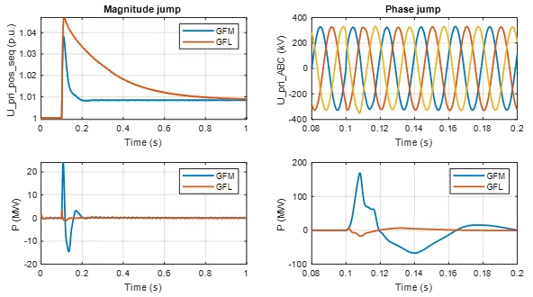
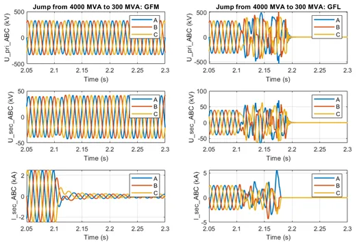
To verify the behavior of the STATCOM regarding the basic grid-forming requirements, different scenarios were investigated. These include angle and amplitude jumps in the grid voltage as well as changes in the grid short-circuit power ratios. (Other scenarios were also analyzed, such as symmetrical and asymmetrical grid faults, setpoint changes, and more, but are not shown here.)
Figure 1 shows the comparison between the grid-forming and grid-following control of the STATCOM Opladen for amplitudes and angular jumps of the grid voltage. In the case of the amplitude jump, it becomes noticeable that the voltage source behavior has a significantly faster response to the change and instantaneously stabilizes the grid voltage with an inherent current contribution. This inherent contribution is offset by the higher-level voltage / reactive power control, resulting in an equal steady-state operating point for both control options. The investigation of the angular jump shows that the grid-forming control immediately provides a stabilizing effect. However, as there is no additional energy storage considered in this project, the active power support is limited, which means that the energy control of the STATCOM limits a larger contribution to protect the internal energy balance.
Outlook for GFM in Germany
Amprion will continue to improve system stability by installing additional synchronous condensers or grid-forming STATCOMs at the transmission level. In addition to the grid-forming capabilities, future STATCOMs will also be installed with additional storage to provide inertia, to contribute to meeting the future system needs. Depending on the development in the system, Amprion plans five to nine additional grid-forming units in the coming years.
To accelerate the development of grid-forming converters, Germany also plans a market-based procurement in the form of a bonus system for grid-forming converters with a contribution to inertia. For this purpose, a common definition of grid-forming capabilities is being developed by the corresponding national standards committee VDE FNN.
[1] “Simulations and Field Experience of Opladen STATCOM with Grid-Forming Behavior”, Mitra et al., CIGRE B4 International SC Meeting and Colloquium, September 2023, Vienna, Austria
Moritz Mittelstaedt
Lead, System Dynamics
Amprion GmbH