
Introduction

As the growth of inverter-based resources (IBRs), such as photovoltaic, wind energy, and batteries, increases in order to decrease the carbon footprint of energy sources, utility protection engineers increasingly ask the question: “Are the protection systems installed at present capable of protecting power systems with a high penetration of IBRs?” Before we can answer that question with any confidence, we need to understand how IBRs behave during power system fault conditions.
Study of Traditional Line Current Protection With IBRs
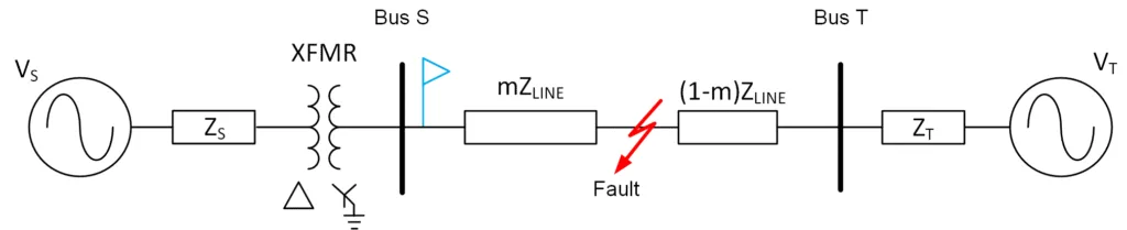
In a recent study the responses of converters from different IBR manufacturers during power system fault conditions were analyzed. The responses of the equipment of each of the IBR manufacturers were different during a power system fault, and none of them behaved like a conventional synchronous generator. Consider the power system shown in Fig. 1.
The filtered oscillography for a metallic Phase-A-to-ground (AG) fault recorded by a protection device at Bus S (the relay terminal) with a synchronous machine as the source behind Terminal S is shown in Fig. 2.
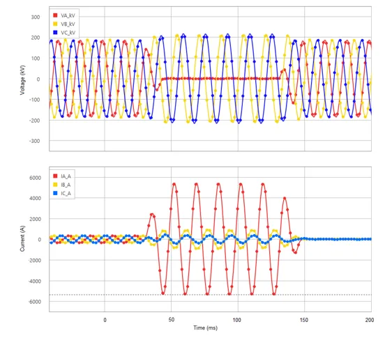
Irrespective of the make, model, or vintage of the synchronous generator source, the filtered oscillographic record for a metallic AG fault at Bus S will be identical (assuming the MVA rating and impedance are identical). If we now replace the synchronous generator behind Terminal S with a full inverter type IBR of identical MVA rating, the filtered oscillographic record for a metallic AG fault at Bus S is shown in Fig. 3.
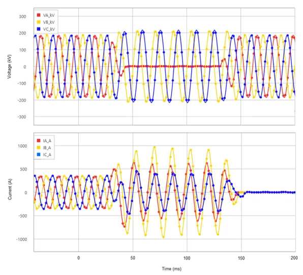
Comparing the two oscillographic records, we can see that the voltage responses are nearly identical, but the currents are significantly different. The power system and the fault resistance determine the voltage at the fault point. The voltage at the relay location is determined by the voltage drop between the fault point and the relay and the voltage at the fault point. The fault current supplied by the source is determined by the impedance between the source and the fault point and the fault resistance. Synchronous generators allow fault current(s) to flow through their windings, whereas IBRs do not; IBRs inject fault current. The magnitude, angle, and frequency of the injected fault current are determined by the IBRs control algorithms. Since the voltage and current at the relay location are not from the same source, their frequency and phase angle may not be coherent. The magnitude of the fault current supplied by the IBR never exceeds 120% of the rating on the IBRs switching devices. The design of the IBR is such that only positive- and negative-sequence currents are injected. The transformer winding configuration at the point of common coupling (PCC) provides a zero-sequence path that allows the flow of zero-sequence current during faults that involve ground. Therefore, the phase currents are a composite of the inverter current (positive- and negative-sequence current) and the system current (zero-sequence current). This composition of the phase current results in some very interesting currents during fault conditions. Analyzing the oscillography in Fig. 3 for a solid metallic AG fault at the relay location, we can agree that this is an AG fault at the relay location ( the A-phase voltage is depressed to near zero and is the voltage with the greatest depression, while the B- and C-phase voltages increase slightly due to the resistance between the transformer neutral and ground). However, if we analyze the phase currents during the fault, we can make a few observations:
-
- The phase currents are almost in phase with one another (this is due to the high zero-sequence current).
- The B-phase current has the highest magnitude, and, from a current point of view, this would imply that it is a Phase-B-to-ground (BG) fault (this is due to the noncoherence between the positive- and negative-sequence current [from the IBR] and the zero-sequence current [from the system]).
- The A-phase current is almost in phase with the pre-fault A-phase voltage (typically, the A-phase current would lag the A-phase voltage by the line angle).
Fault currents injected by an IBR are significantly different from the fault current generated by a conventional synchronous generator. Traditional protection algorithms rely on the magnitude of the fault current generated and the angle between the phase currents or the angle between the phase currents and voltages. Most of these relationships no longer hold true, and traditional protection algorithms such as overcurrent, directional, and distance elements can no longer be relied upon to provide secure and dependable protection. Conventional protection also assumes that the fault current and voltage are coherent with one another.
However, traditional line current differential protection still operates reliably and dependably if one or more of the line terminals is connected to a strong synchronous generator source. The main reason for this is that line current differential protection is unit protection and therefore it requires current information from all terminals that make up the zone of protection. The strong synchronous generator source terminal will provide the bulk of the fault current flowing into the protected zone and thereby develop a large enough differential or operating current to initiate dependable operation of the line current differential protection. Should the communications infrastructure (channel) not be able to support the bandwidth requirements for line current differential protection, the channel will be able to support a direct transfer trip (DTT) pilot communications protection scheme. In a DTT scheme, the strong terminal (connected to a conventional synchronous generator source) will issue a trip command via the communications infrastructure to the remote terminals when the strong terminal detects a fault in its zone of protection.
New Protection Technologies for IBR Challenges
Two emerging technologies offer a possible solution for the protection of power systems with a high penetration of IBRs. These are time-domain (TD) and traveling-wave (TW) protection. TD or incremental-quantity protection elements not only offer the advantage that these elements are not sensitive to load, but they also respond rapidly (in less than one cycle). This proves advantageous in these systems in that the IBR control algorithms require about one-quarter of a power system cycle to respond and curtail the fault current injected. This response time of the IBR control algorithm may be enough time for these elements to identify the fault loop, the direction of the fault, and the possible impedance to the fault.
For TW protection, the magnitude and polarity of the VTW launched are dependent on the magnitude and polarity of the voltage at the instant of the fault at the fault location. The larger the magnitude of the voltage at the time of the fault, the larger the magnitude of VTW, which is opposite to the polarity of the voltage at the instant of the fault. The magnitude of the ITW launched is directly proportional to the VTW and inversely proportional to the characteristic impedance (ZC) of the power line. Since ZC is predominantly a positive real number, the polarity of the ITW and VTW are the same. So, as can be seen, the VTW and ITW launched due to a power system fault are only dependent on the ZC of the line in which they are launched and are independent of the sources in the power system.
Both these emerging technologies show promise to provide dependable and secure protection for power systems with a large penetration of IBRs.
Normann Fischer, Fellow Power Engineer
R&D Technologies
Schweitzer Engineering Laboratories