
The majority of devices that are based on power electronics (Statcoms, HVDC links, batteries, wind plants, PV solar plants, variable speed motors, converter-based loads, etc.) do not contribute synchronous inertial response to the system. As the grid transforms from the retirement of conventional thermal generation and additions of converter-based resources, it is prudent to consider the way that this transformation will change the coordinated needs for understanding and addressing frequency response, weak system issues and other aspects related to our historic use of synchronous inertial response. The objective of this blog is to identify technical issues as increasing amounts of wind/solar/converter based generation are added to a system, to show solutions for these issues, and to encourage additional research on this subject.
These devices all use VSC (Voltage Source Converters) with a CC (Constant Current) inner control loop (see Figure 1 below). If the system voltage phase angle shifts, the converter CC inner controller will very quickly adjust itself to keep its current constant (so quickly in fact that this controller is ignored in most transient stability simulations). This is in stark contrast to a conventional synchronous generator, which has an equivalent circuit of an “E behind Z” (a constant voltage source) – i.e. when the terminal voltage phase angle shifts, the generator power will change and E is relatively constant in the immediate post-transient period.
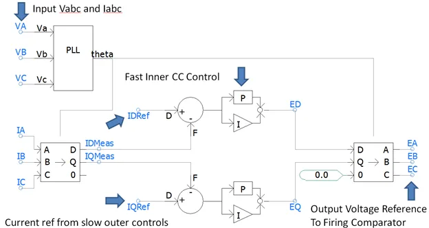
Figure 1 – Conventional VSC CC (Constant Current) Inner Controller
Today’s power systems are facing (or will face) a major road block – weak system or SCR (Short Circuit Ratio) limitations. There is a limit on the percentage of wind/solar with a CC inner control loop that can be added to a conventional power system due to “weak grid issues”. Problems observed in the field include oscillations and instabilities, prolonged over-voltages or voltage collapse during fault recovery, protection operations and failure to ride through disturbances.
This used to be a localized problem with large renewable projects in isolated weak parts of the grid, but now occurs on a larger scale. Many places in the world have already hit this limit, including parts of Texas, Northeast USA, Australia and many others. Even in distributed generation systems (with rooftop solar or other generation) these limits are also fast approaching (Hawaii, for example); the ratio of converter fed to conventional generation is increasing worldwide.
This limit (SCR or weak system considerations) is almost always ignored in most high-level energy discussions – these discussions focus more on renewable penetration levels and energy storage requirements, but ignore the technical reality that a system without conventional synchronous generation simply will not work today without some major modifications! In these discussions, BES (Battery Energy Storage) is presented as a big part of the solution, despite the fact that most (but not all!) BES’s are also using converters with CC controllers.
The solution to weak system concerns being considered in many places is to keep minimum levels of strong rotating thermal generation, or to add “conventional inertia” via synchronous condensers (indeed this business is booming). There is another solution however – CV (Constant Voltage) control systems for VSC converters.
CV VSC controllers can be used instead of CC controllers – there are already a few “niche” applications where this has been done:
- CV control characteristics were used in an early Hawaii Wind study (Dennis Woodford designed a 200 MW VSC HVDC controller which could accommodate 200 MW of wind, yet be connected to a grid with a SCMVA of only 20 (an SCR of 0.05!) – this project did not proceed to construction.
- Offshore wind fed into VSC/HVDC Converters (the VSC converter becomes a “grid forming” converter, so all wind VSC converters synchronize to the VSC/HVDC link) – no conventional synchronous generators are needed (ie SCR = 0).
- Mackinac VSC/HVDC converter (uses a unique CV-like characteristic to automatically maintain system stability during major contingencies/outages on the weak side and has an automatic power order runback scheme).
- Some BES projects (including a large BES in South Australia, which uses a CV characteristic and can transition from grid-following mode to grid-forming mode without tripping, and can immediately meet power requirements in an island).
In general CV methods can be distinguished from “grid-forming” converters – CV methods can control real power by relatively slow/smooth modulation of the voltage source angle, which inherently provides a stabilizing, inertia-like quality. Grid-forming and grid-following should not be considered black and white modes of operation, but there is middle ground with programmable system strength constants in the controls. This is not to be confused with “synthetic inertia” efforts, where we make converters look like rotating machines with “1/(2*H*S)” standard electro-mechanical swing equations. CV converter control can do much better than mimicking machines (why would you deliberately design a converter to be oscillatory?), but the key CV advantages are similar.
The above examples of CV VSC converters all utilize one relatively large converter (wouldn’t adding huge BES’s to our grid be nice?!), or VSC/HVDC links which can use CV control methods on one side (transferring power variability to the other/strong side which must have fast DC voltage control using conventional fast CC control methods). Our research shows that the same CV-like advantages can be achieved with distributed VSC converters (i.e. wind or solar/batteries) – we have demonstrated distributed wind or solar plants that can be designed to feed 100% passive loads (i.e. an SCR of 0).
There are considerable challenges ahead (as coal/natural gas retires and we get more converter fed energy sources) – it may seem simple for the wind/solar manufacturers to switch their controllers to CV methods (after all it is only a controller software change – right?). However, it may not be that simple. When you hold the converter voltage to be more constant, the IGBT currents are not controlled as tightly anymore, so controls may be required to transition back to CC control during faults and other big dynamic events. Similarly, it may be necessary to over-size the converters (or under-utilize capability) to increase IGBT current margins – both are very costly in a very competitive industry. Also, communication/coordination between nearby converters may be required, and there is a vast body of existing renewable generation which must continue to work with older control schemes. All of this can be done, but needs research, investment and cooperation!
A useful conceptual exercise is to design a large power system/grid that has only wind/solar and BES’s (i.e. redesign the future grid from a “blank slate”). This may not be practical (due to costs of energy storage), but it is a good theoretical exercise nonetheless, and helps us defines the direction to head toward. CV converters (in wind, solar, VSC/HVDC, BES etc.) can achieve this.
The control systems in wind, solar and BES converters need to evolve to CV methods in order to meet the challenges of tomorrow’s grid and to ensure future system reliability.
Garth Irwin
Vice-President
Electranix Corporation
[email protected]